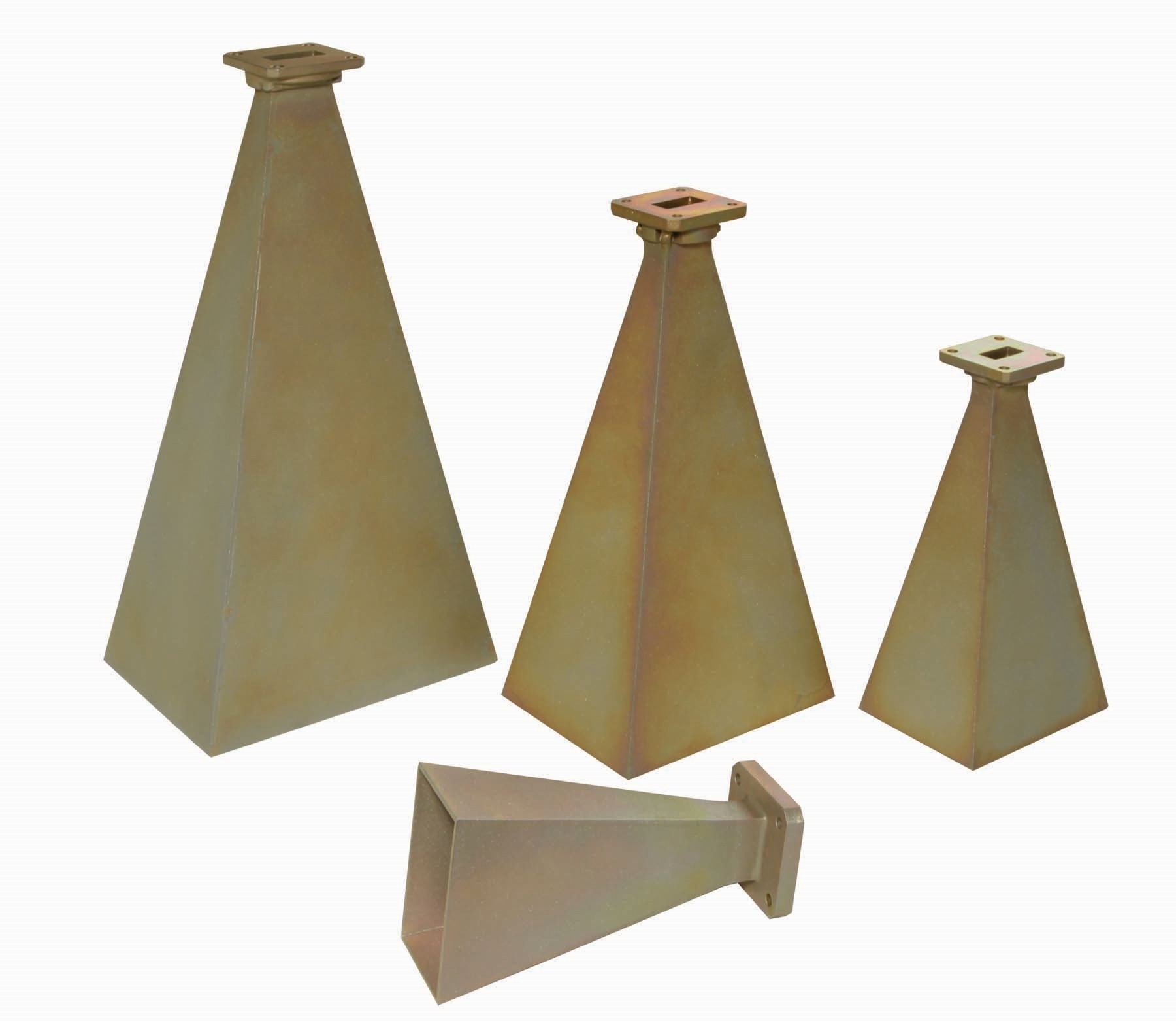
| Standard Gain Horn Antenna | ||||
|---|---|---|---|---|
|
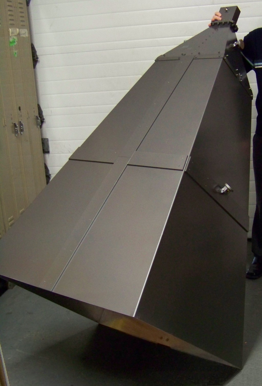
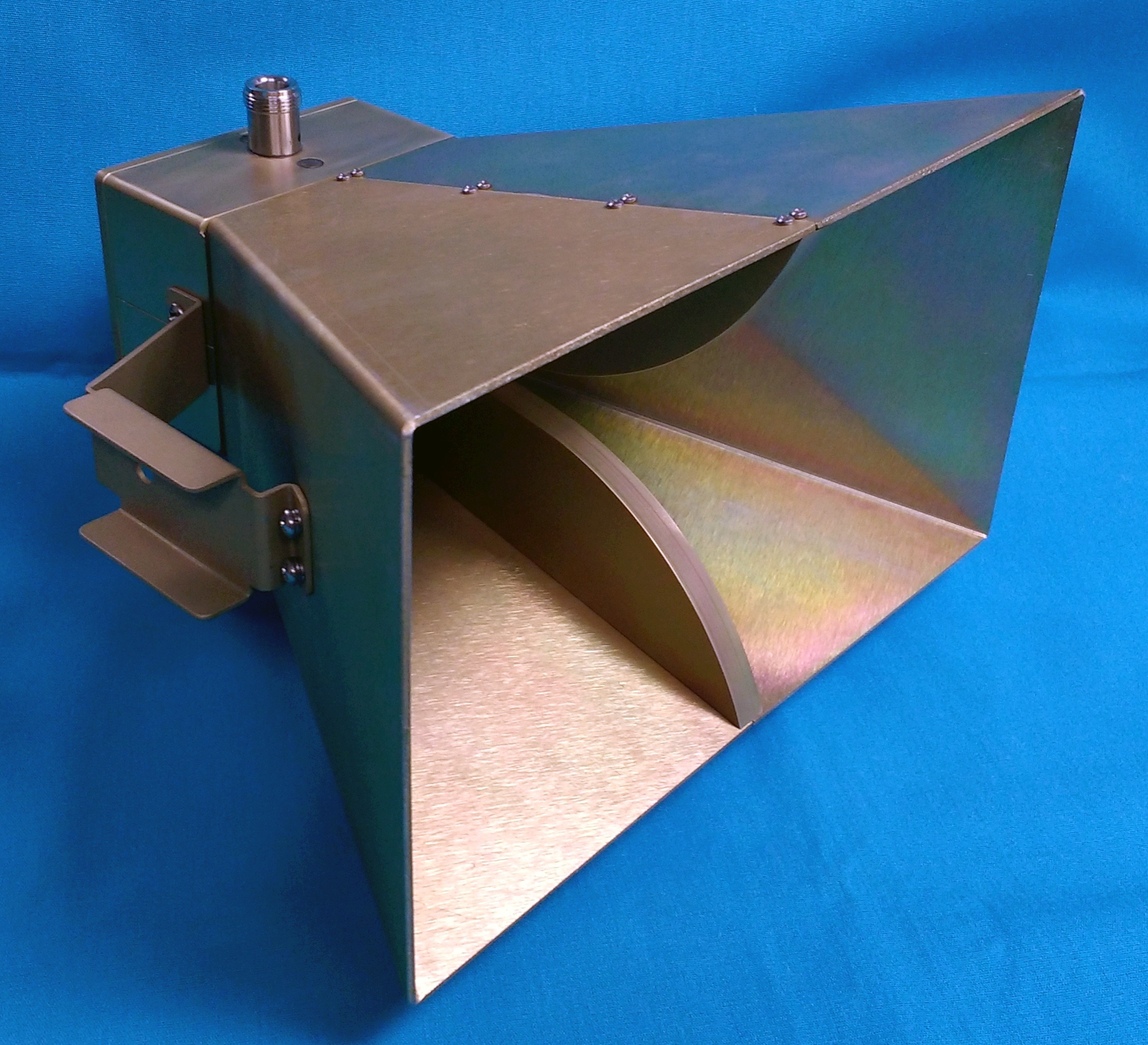
Special Narda-MITEQ Horn Antenna
|
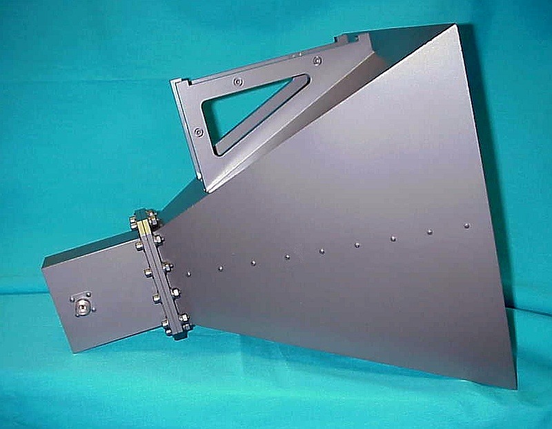
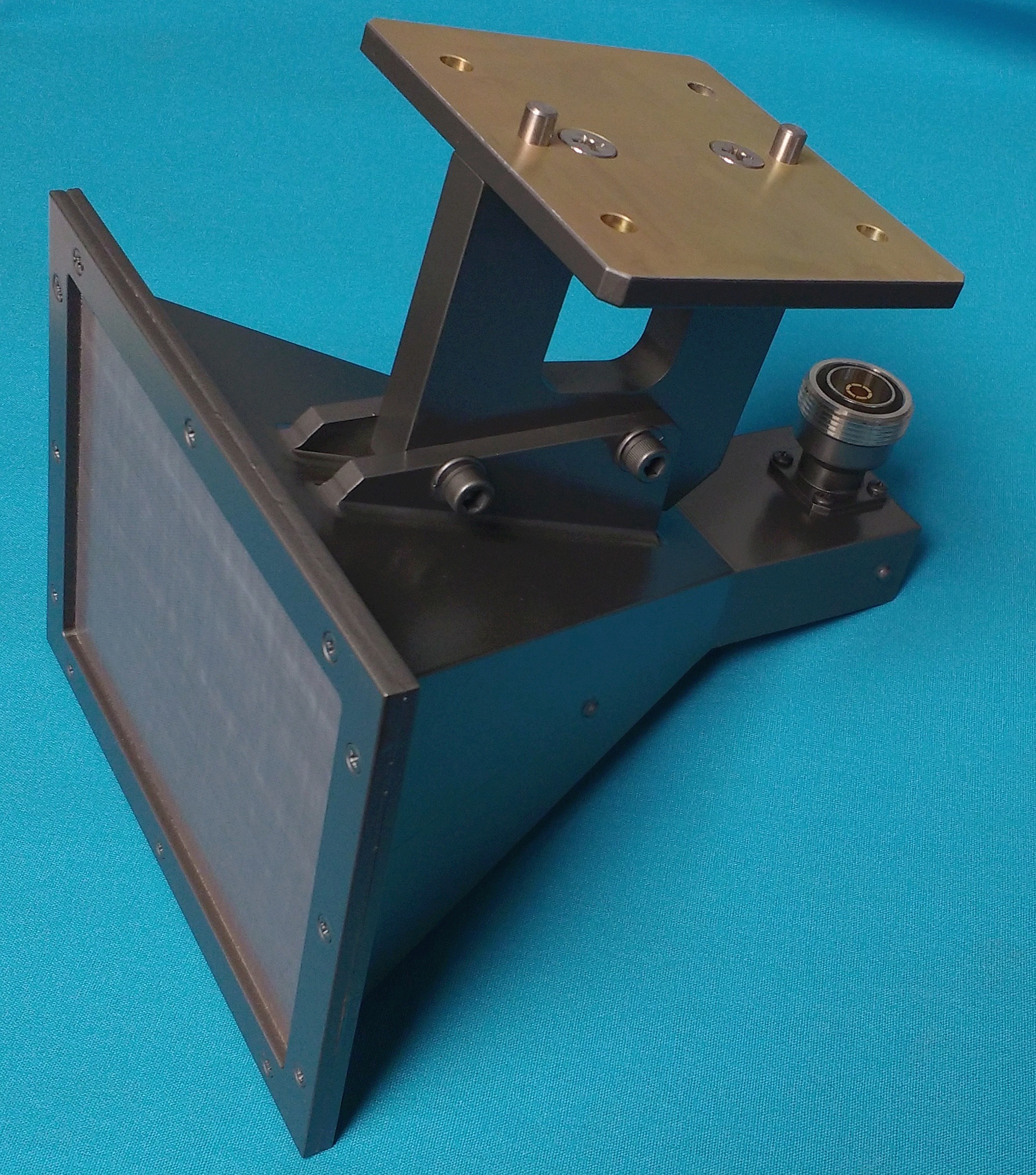
Horn Antenna with Radome Cover |
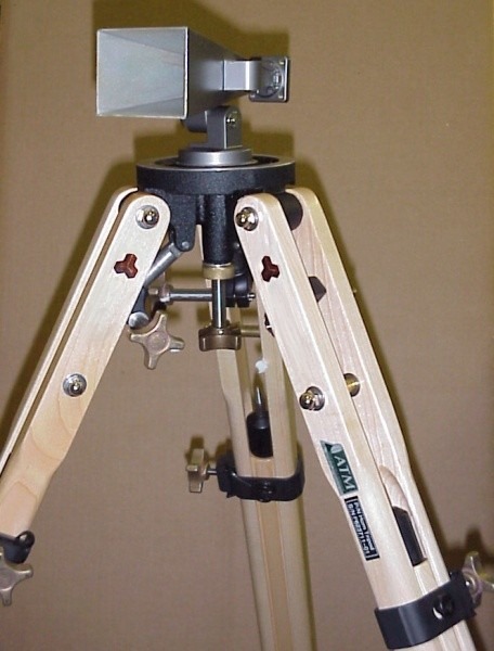
Tripod and Bracket Mounting |
|
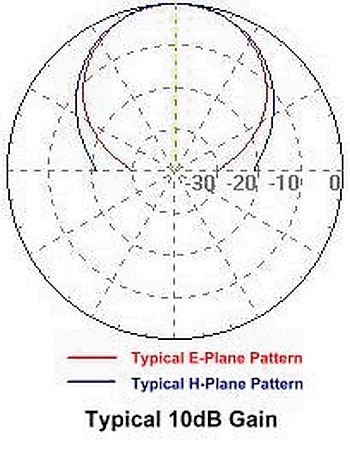
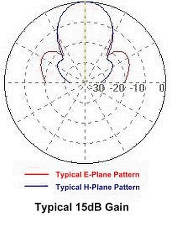
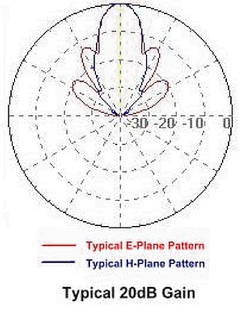
click thumbnail for typical gain pattern:
|
|
|||


| Standard Gain Horn Antenna - Standard Models | ||||||||||||
|---|---|---|---|---|---|---|---|---|---|---|---|---|
| WG Size | Frequency (GHz) |
Model No.* | Gain (dB) |
3dB Beam |
Est. |
 |
Far Field (M) @ Low to High Freq. |
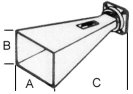
Outline Drawing |
Typical Data |
|||
| E-Plane | H-Plane | Size (In)** | ||||||||||
| A | B | C** | ||||||||||
| WR975 | 0.75 - 1.12 | 975-441-2 | 14 | 34° | 39° | 22.58 | 19.60 | 24.0 | 1.65 - 2.46 | Data | ||
| WR650 | 1.12 - 1.70 | 650-440-2 | 10 | 65.1° | 45.6° | 5.0 lbs | 12.14 | 6.07 | 15.98 | 0.71 - 1.08 | Data | |
| WR650 | 1.12 - 1.70 | 650-441-2 | 15 | 31.1° | 29.0° | 16 lbs | 19.69 | 13.78 | 29.38 | 1.87 - 2.84 | Data | |
| WR510 | 1.45 - 2.20 | 510-440-2 | 10 | 52.4° | 52.4° | 8.07 | 6.00 | 13.00 | 0.4 - 0.62 | |||
| WR510 | 1.45 - 2.20 | 510-441-2 | 15 | 30.8° | 30.8° | 14.15 | 10.68 | 26 | 1.25 - 1.90 | |||
| WR430 | 1.70 - 2.60 | 430-440-2 | 10 | 64.8° | 45.4° | 2.3 lbs | 8.00 | 4.00 | 10.50 | 0.47 - 0.72 | Data | |
| WR430 | 1.70 - 2.60 | 430-441-2 | 15 | 33.1° | 32.0° | 15.2 lbs | 11.60 | 8.30 | 23.00 | 0.98 - 1.51 | Data | |
| WR430 | 1.70 - 2.60 | 430-442-2 | 20 | 17.3° | 17.4° | 26.5 lbs | 22.0 | 16.0 | 40.5 | 3.54 - 5.42 | Data | |
| WR340 | 2.20 - 3.30 | 340-440-2 | 10 | 60.0° | 49.3° | 5.71 | 3.43 | 9.00 | 0.31 - 0.46 | |||
| WR340 | 2.20 - 3.30 | 340-441-2 | 15 | 32.2° | 30.8° | 5.2 lbs | 9.45 | 6.69 | 15.63 | 0.85 - 1.27 | Data | |
| WR340 | 2.20 - 3.30 | 340-442-2 | 20 | 18.5° | 16.3° | 18.79 | 11.81 | 35.0 | 3.34 - 5.01 | |||
| WR284 | 2.60 - 3.95 | 284-440-6 | 10 | 50.8° | 54.1° | 1.0 lbs | 4.33 | 3.46 | 7.50 | 0.21 - 0.32 | Data | |
| WR284 | 2.60 - 3.95 | 284-441-6 | 15 | 31.0° | 30.6° | 2.8 lbs | 7.96 | 5.83 | 15.34 | 0.71 - 1.08 | Data | |
| WR284 | 2.60 - 3.95 | 284-442-6 | 20 | 17.2° | 16.5° | 8.5 lbs | 15.57 | 10.67 | 29.75 | 2.71 - 4.12 | Data | |
| WR229 | 3.30 - 4.90 | 229-440-2 | 10 | 58.6° | 51.9° | 3.62 | 2.36 | 6.45 | 0.19 - 0.28 | |||
| WR229 | 3.30 - 4.90 | 229-441-2 | 15 | 32.7° | 32.4° | 2.8 lbs | 6.00 | 4.41 | 10.40 | 0.51 - 0.76 | Data | |
| WR229 | 3.30 - 4.90 | 229-442-2 | 20 | 17.1° | 16.7° | 5.0 lbs | 12.25 | 8.60 | 23.50 | 2.13 - 3.16 | Data | |
| WR187 | 3.95 - 5.85 | 187-440-6 | 10 | 55.0° | 54.1° | 2.89 | 2.12 | 5.50 | 0.14 - 0.21 | Data | ||
| WR187 | 3.95 - 5.85 | 187-441-6 | 15 | 33.8° | 33.3° | 4.88 | 3.57 | 9.40 | 0.40 - 0.60 | Data | ||
| WR187 | 3.95 - 5.85 | 187-442-6 | 20 | 18.9° | 19.2° | 2.5 lbs | 8.92 | 6.53 | 14.925 | 1.35 - 2.00 | Data | |
| WR159 | 4.90 - 7.05 | 159-440-2 | 10 | 59.8° | 48.3° | 2.68 | 1.58 | 4.28 | 0.15 - 0.22 | Data | ||
| WR159 | 4.90 - 7.05 | 159-441-2 | 15 | 31.3° | 30.8° | 2.4 lbs | 4.33 | 3.15 | 8.00 | 0.40 - 0.57 | Data | |
| WR159 | 4.90 - 7.05 | 159-442-2 | 20 | 14.3° | 16.9° | 9.80 | 7.64 | 11.73 | 2.03 - 2.91 | Data | ||
| WR137 | 5.85 - 8.20 | 137-440-2 | 10 | 55.1° | 54.2° | 2.02 | 1.48 | 3.15 | 0.10 - 0.14 | |||
| WR137 | 5.85 - 8.20 | 137-441-2 | 15 | 33.7° | 33.2° | 3.42 | 2.50 | 6.51 | 0.29 - 0.41 | Data | ||
| WR137 | 5.85 - 8.20 | 137-442-2 | 20 | 18.7° | 18.8° | 1.5 lbs | 6.26 | 4.57 | 12.19 | 0.99 - 1.38 | Data | |
| WR112 | 7.05 - 10.0 | 112-440-6 | 10 | 56.8° | 55.2° | 1.63 | 1.18 | 2.55 | 0.08 - 0.11 | |||
| WR112 | 7.05 - 10.0 | 112-441-6 | 15 | 32.4° | 32.0° | 2.93 | 2.15 | 6.65 | 0.26 - 0.37 | Data | ||
| WR112 | 7.05 - 10.0 | 112-442-6 | 20 | 19.3° | 19.3° | 0.75 lbs | 4.97 | 3.64 | 10.78 | 0.75 - 1.06 | Data | |
| WR102 | 7.00 - 11.0 | 102-440-6 | 10 | 55.5° | 54.1° | 1.58 | 1.14 | 3.00 | 0.07 - 0.12 | |||
| WR102 | 7.00 - 11.0 | 102-441-6 | 15 | 29.6° | 29.3° | 3.04 | 2.23 | 6.00 | 0.28 - 0.44 | |||
| WR102 | 7.00 - 11.0 | 102-449-6/17 | 17 | 26.2° | 25.3° | 3.60 | 2.54 | 5.25 | 0.39 - 0.61 | |||
| WR102 | 7.00 - 11.0 | 102-442-6 | 20 | 17.0° | 16.7° | 5.57 | 3.94 | 11.13 | 1.00 - 1.57 | |||
| WR90 | 8.20 - 12.4 | 90-440-6 | 10 | 48.5° | 47.4° | 1.58 | 1.15 | 2.01 | 0.09 - 0.13 | Data | ||
| WR90 | 8.20 - 12.4 | 90-441-6 | 15 | 29.3° | 29.0° | 0.25 lbs | 2.66 | 1.95 | 5.46 | 0.25 - 0.38 | Data | |
| WR90 | 8.20 - 12.4 | 90-442-6 | 20 | 16.1° | 16.5° | 0.75 lbs | 4.87 | 3.62 | 10.06 | 0.84 - 1.27 | Data | |
| WR75 | 10.0 - 15.0 | 75-440-6 | 10 | 50.2° | 49.2° | 1.26 | 0.92 | 1.94 | 0.07 - 0.10 | |||
| WR75 | 10.0 - 15.0 | 75-441-6 | 15 | 35.4° | 28.5° | 2.25 | 1.33 | 4.69 | 0.22 - 0.33 | Data | ||
| WR75 | 10.0 - 15.0 | 75-442-6 | 20 | 16.3° | 17.2° | 0.6 lbs | 3.88 | 2.98 | 8.00 | 0.65 - 0.97 | Data | |
| WR62 | 12.4 - 18.0 | 62-440-6 | 10 | 55.3° | 50.9° | 0.5 lbs | 1.00 | 0.68 | 1.00 | 0.05 - 0.08 | ||
| WR62 | 12.4 - 18.0 | 62-441-6 | 15 | 30.1° | 31.2° | 0.15 lbs | 1.69 | 1.30 | 2.46 | 0.15 - 0.22 | Data | |
| WR62 | 12.4 - 18.0 | 62-449-6/17.5 | 17.5 | 23.0° | 24.5° | 2.19 | 1.72 | 3.46 | 0.25 - 0.37 | |||
| WR62 | 12.4 - 18.0 | 62-442-6 | 20 | 18.8° | 18.9° | 0.25 lbs | 2.88 | 2.11 | 5.75 | 0.44 - 0.64 | Data | |
| WR51 | 15.0 - 22.0 | 51-440-6 | 10 | 55.1° | 54.2° | 0.77 | 0.56 | 1.43 | 0.04 - 0.06 | Data | ||
| WR51 | 15.0 - 22.0 | 51-441-6 | 15 | 32.0° | 31.8° | 1.36 | 1.00 | 2.84 | 0.12 - 0.17 | |||
| WR51 | 15.0 - 22.0 | 51-442-6 | 20 | 16.9° | 18.0° | 0.35 lbs | 2.51 | 1.93 | 4.88 | 0.41 - 0.51 | Data | |
| WR42 | 18.0 - 26.5 | 42-440-6 | 10 | 58.0° | 57.0° | 0.1 lbs | 0.60 | 0.44 | 1.25 | 0.03 - 0.04 | ||
| WR42 | 18.0 - 26.5 | 42-441-6 | 15 | 31.3° | 31.5° | 1.14 | 0.85 | 2.37 | 0.10 - 0.15 | Data | ||
| WR42 | 18.0 - 26.5 | 42-449-6/16 | 16 | 27.9° | 27.9° | 1.29 | 0.96 | 3.42 | 0.13 - 0.19 | |||
| WR42 | 18.0 - 26.5 | 42-442-6 | 20 | 17.5° | 17.8° | 0.13 lbs | 2.13 | 1.56 | 4.00 | 0.35 - 0.52 | Data | |
| WR34 | 22.0 - 33.0 | 34-440-6 | 10 | 54.1° | 53.2° | 0.2 lbs | 0.53 | 0.39 | 1.13 | 0.03 - 0.04 | ||
| WR34 | 22.0 - 33.0 | 34-441-6 | 15 | 23.1° | 40.8° | 0.95 | 0.70 | 2.12 | 0.09 - 0.13 | Data | ||
| WR34 | 22.0 - 33.0 | 34-442-6 | 20 | 17.0° | 17.4° | 0.29 lbs | 1.76 | 1.29 | 3.56 | 0.29 - 0.44 | Data | |
| WR28 | 26.5 - 40.0 | 28-440-6 | 10 | 54.2° | 54.4° | 0.01 lbs | 0.42 | 0.315 | 1.00 | 0.02 - 0.03 | ||
| WR28 | 26.5 - 40.0 | 28-441-6 | 15 | 32.1° | 31.3° | 0.76 | 0.55 | 1.87 | 0.07 - 0.10 | Data | ||
| WR28 | 26.5 - 40.0 | 28-442-6 | 20 | 16.7° | 18.3° | 0.13 lbs | 1.38 | 1.01 | 3.12 | 0.22 - 0.33 | Data | |
| WR22 | 33.0 - 50.0 | 22-443-6R | 23 | 9.6° | 11.7° | 0.25 lbs | 2.170 | 1.656 | 4.07 | 0.669 - 1.013 | ||
| WR19 | 40.0 - 60.0 | 19-443-6R | 23 | 9.5° | 12.0° | 1.821 | 1.39 | 3.48 | 0.561 - 0.586 | |||
| WR15 | 50.0 - 75.0 | 15-443-6R | 23 | 9.5° | 12.0° | 0.20 lbs | 1.432 | 1.094 | 2.78 | 0.440 - 0 662 | Data | |
| WR12 | 60.0 - 90.0 | 12-443-6R | 23 | 9.5° | 12.0° | 1.182 | 0.902 | 2.35 | 0.310 - 0.541 | |||
| WR10 | 75.0 - 110.0 | 10-443-6R | 23 | 9.5° | 12.0° | 0.15 lbs | 0.969 | 0.74 | 1.94 | 0.298 - 0.445 | ||
| WR 8 | 90.0 - 140.0 | 08-443-6R | 23 | 9.5° | 12.0° | 0.775 | 0.591 | 1.56 | 0.236 - 0.362 | |||
| WR5 | 140.0 - 220.0 | 05-443-6R | 23 | 9.5° | 12.0° | 0.494 | 0.377 | 1.04 | 0.147 - 0.284 | |||
|
* The Standard Model Numbers above are the most common parts ordered for size, material and flange. However, these models can easily be altered to accommodate your needs by using the Model # code system to the left. Above models are not supplied with calibration data. Select /CAL option to receive actual Gain vs. Frequency taken in the far field. Click this link for a sample of data: "Calibration Data Sample" ** Overall length can vary depending on flange type. *** Gain and 3dB Beam width values have been calculated by computer simulation. **** More than one option per Horn is possible. For example: |
||||||||||||||||||||||||||||||
| High Gain Horn Antenna - Standard Models | ||||||||||||
|---|---|---|---|---|---|---|---|---|---|---|---|---|
| WG Size | Frequency (GHz) |
Model No. | Gain (dB) |
3dB Beam Width*** |
Est. Weight |
 |
Far Field(M) @ Low to High Freq. |
Outline Drawing |
Typical Data |
|||
| E-Plane | H-Plane | Size (In)** | ||||||||||
| A | B | C** | ||||||||||
| WR284 | 2.60 - 3.95 | 284-443-6 | 24 | 7.9° | 9.6° | 60 lbs | 31.10 | 25.98 | 72.00 | 10.8 – 16.4 | ||
| WR229 | 3.30 - 4.90 | 229-443-2 | 24 | 7.7° | 9.4° | 28.35 | 20.47 | 64.50 | 11.4 – 16.9 | |||
| WR187 | 3.95 - 5.85 | 187-443-6 | 24 | 7.2° | 9.7° | 40 lbs | 26.38 | 18.90 | 58.00 | 11.8 – 17.5 | ||
| WR159 | 4.90 - 7.05 | 159-443-2 | 24 | 7.2° | 10.8° | 24.41 | 17.72 | 51.00 | 12.5 – 18.1 | |||
| WR137 | 5.85 - 8.20 | 137-443-2 | 24 | 7.6° | 10.1° | 20 lbs | 17.32 | 12.50 | 37.00 | 7.5 – 10.6 | ||
| WR112 | 7.05 - 10.0 | 112-443-6 | 24 | 9.8° | 10.9° | 3.13 lbs | 11.00 | 7.50 | 21.50 | 3.7 – 5.2 | ||
| WR102 | 7.00 - 11.0 | 102-443-6 | 24 | 9.5° | 10.8° | 10.63 | 7.40 | 21.00 | 3.4 – 5.3 | |||
| WR90 | 8.20 - 12.4 | 90-443-6 | 24 | 8.8° | 10.6° | 3.13 lbs | 10.0 | 7.00 | 20.20 | 3.5 – 5.3 | Dwg | |
| WR75 | 10.0 - 15.0 | 75-443-6 | 24 | 8.9° | 10.5° | 8.07 | 5.73 | 17.00 | 2.8 – 4.2 | |||
| WR62 | 12.4 - 18.0 | 62-443-6 | 24 | 9.4° | 10.7° | 1.8 lbs | 6.10 | 4.44 | 13.00 | 2.0 – 2.9 | Dwg1 Dwg2 | |
| WR51 | 15.0 - 22.0 | 51-443-6 | 24 | 10.1° | 8.6° | 5.28 | 3.98 | 12.00 | 1.8 – 2.6 | |||
| WR42 | 18.0 - 26.5 | 42-443-6 | 25 | 8.1° | 9.5° | 4.45 | 3.54 | 11.05 | 1.53 – 2.3 | Dwg | Data | |
| WR34 | 22.0 - 33.0 | 34-443-6 | 25 | 8.6° | 9.6° | 3.70 | 2.68 | 9.00 | 1.3 – 1.94 | |||
| WR28 | 26.5 - 40.0 | 28-443-6 | 25 | 8.3° | 9.7° | 2.97 | 2.34 | 7.10 | 1.0 – 1.52 | Dwg | Data | |
| WR22 | 33.0 - 50.0 | 22-443-6R | 23 | 9.6° | 11.7° | 0.25 lbs | 2.170 | 1.656 | 4.07 | 0.67 – 1.01 | ||
| WR19 | 40.0 - 60.0 | 19-443-6R | 23 | 9.5° | 12.0° | 1.821 | 1.39 | 3.48 | 0.57 – 0.86 | |||
| WR15 | 50.0 - 75.0 | 15-443-6R | 23 | 9.5° | 12.0° | 0.20 lbs | 1.432 | 1.094 | 2.78 | 0.44 – 0.66 | ||
| WR12 | 60.0 - 90.0 | 12-443-6R | 23 | 9.5° | 12.0° | 1.182 | 0.902 | 2.35 | 0.36 – 0.54 | |||
| WR10 | 75.0 - 110.0 | 10-443-6R | 23 | 9.5° | 12.0° | 0.15 lbs | 0.969 | 0.74 | 1.94 | 0.30 – 0.44 | ||
| WR 8 | 90.0 - 140.0 | 08-443-6R | 23 | 9.5° | 12.0° | 0.775 | 0.591 | 1.56 | 0.23 – 0.36 | |||
| WR 5 | 140.0 - 220.0 | 05-443-6R | 23 | 9.5° | 12.0° | 0.494 | 0.377 | 1.04 | 0.15 – 0.23 | |||
|
* The Standard Model Numbers above are the most common parts ordered for size, material and flange. However, these models can easily be altered to accommodate your needs by using the Model # code system to the left. Above models are not supplied with calibration data. Select /CAL option to receive actual Gain vs. Frequency taken in the far field. Click this link for a sample of data: "Calibration Data Sample" ** Overall length can vary depending on flange type. *** Gain and 3dB Beam width values have been calculated by computer simulation. **** More than one option per Horn is possible. For example: |
||||||||||||||||||||||||||||||
| Wide Band Antennas | ||||||||||||||||||||
|---|---|---|---|---|---|---|---|---|---|---|---|---|---|---|---|---|---|---|---|---|
|
|
|||||||||||||||||||
|
||||||||||||||||||||
| Input W/G Size or Coax. Conn. Type |
Freq. (GHz) |
Model No. | Gain (dB) Low to High Freq |
3 dB Beam Width* [Low-High Freq.] |
Test Dist. (M) *** |
Far Field (M) *** |
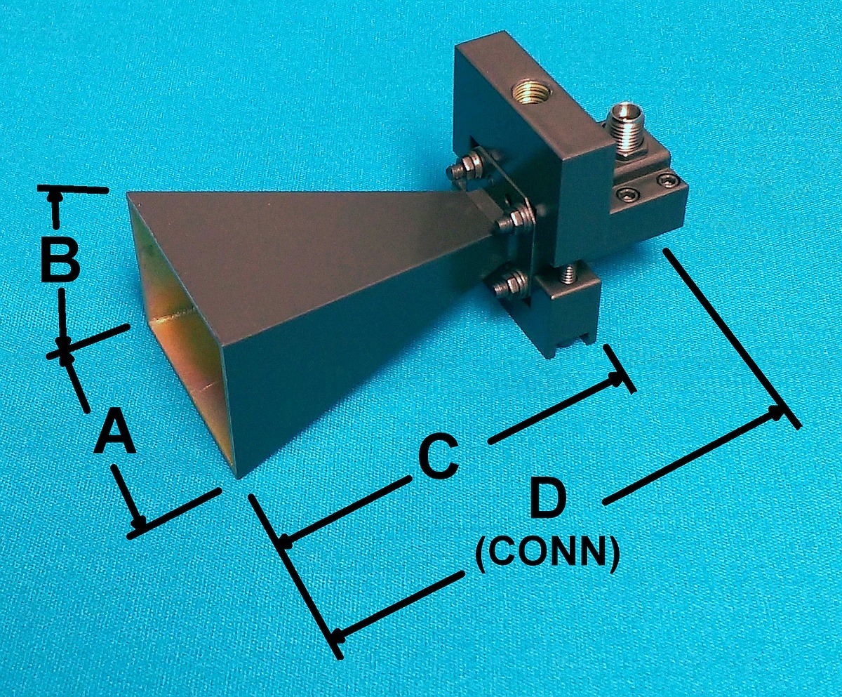
Est. Weight | A | B | C | D | Outline | Typical Data |
|||||||
| E-Plane (deg.) |
H-Plane (deg.) |
|||||||||||||||||||
| TYPE-N | 0.7 - 18 | 07-18-440-NF | 1.4-15 | 48 | 30 | 7.14 | 3.5 lbs | 9.6 | 5.6 | 11.0 | Dwg | Data | ||||||||
| TYPE-N | 0.75 - 1.12 | 975-441-NF | 12.2-15.1 | 40-28 | 46-32 | 2.458 | 20 lbs | 22.58 | 19.60 | 23.7 | Dwg | Data | ||||||||
| TYPE-N | 1.0 - 2.5 | 150-441EM-NF | 9-11 | 45-21 | 51-23 | 1.6 | 2.6 | 15.50 | 13.30 | 13.13 | 16.65 | Dwg | Data | |||||||
| TYPE-N | 1.0 - 2.5 | 150-442EM-NF | 17-20 | 17-9 | 23-11 | 13.5 | 35.50 | 35.50 | 75.2 | 78.7 | Dwg | |||||||||
| TYPE-N | 1.0 - 12.0 | 1-12-440EM-NF | 8-12 | 63-21 | 61-20 | 1 | 4.7 | 9.50 | 5.40 | 6.94 | 7.0 | Dwg | Data | |||||||
| 7/16 (F) | 2.0 - 4.0 | 2-4-442EM-7/16 | 17-22 | 25-13 | 21-12 | 6.053 | 25 lbs | 18.78 | 11.81 | 40.02 | Dwg | |||||||||
| 7/16 (F) | 4.0 - 6.0 | 4-6-442EM-7/16 | 17.5-20.5 | 23-15.5 | 23-16 | 2.055 | 3.5 lbs | 8.92 | 6.53 | 18.25 | Dwg | |||||||||
| 7/16 (F) | 6.0 - 8.0 | 6-8-442EM-7/16 | 18-20 | 22-16.5 | 22-16.6 | 1.349 | 2.5 lbs | 6.26 | 4.57 | 15.25 | Dwg | |||||||||
| WRD250 | 2.5 - 7.5 | 250-441-C3 | 7-13 | 59-22 | 58-22 | 1 | 1 | 5.25 | 3.84 | 6.73 | - | Dwg | ||||||||
| TYPE-N | 2.5 - 7.5 | 250-441EM-NF | 7-13 | 59-22 | 58-22 | 1 | 1 | 2.0 lbs | 5.25 | 3.84 | 6.73 | 8.0 | Dwg | Data | ||||||
| WRD250 | 2.5 - 7.5 | 250-442-C3 | 18-20 | 17-9 | 17-16 | 3 | 15.6 | 22.0 | 15.0 | 33.4 | - | Dwg | Data | |||||||
| TYPE-N | 2.5 - 8.0 | 250-442EM-NF | 18-20 | 17-9 | 17-9 | 3 | 16.665 | 23 lbs | 22.0 | 15.0 | 33.4 | 36.0 | Dwg | Data | ||||||
| WRD650 | 6.5 - 18.0 | 650-442-C3 | 19.0-24 | 16-8 | 16-13 | 3.796 | 7.0 | 5.00 | 12.13 | Dwg | ||||||||||
| TYPE-N | 6.5 - 18.0 | 650-442EM-NF | 19.0-24 | 16-8 | 16-13 | 3.796 | 7.0 | 5.00 | 12.13 | 13.55 | Dwg | |||||||||
| WRD750 | 7.5 - 18.0 | 750-442-C3 | 20.5-24 | 16-8 | 16-13 | 3.796 | 2.3 lbs | 7.00 | 5.00 | 12.13 | - | Dwg | ||||||||
| TYPE-N | 7.5 - 18.0 | 750-442EM-NF | 20.5-24 | 16-8 | 16-13 | 3.796 | 7.00 | 5.00 | 12.13 | 13.55 | Dwg | Data | ||||||||
| WRD180 | 18.0 - 40.0 | 180-442-C3 | 14-19 | 32-15 | 30-15 | 1 | 0.38 | 1.47 | 1.05 | 2.47 | - | |||||||||
| K-TYPE (F) | 18.0 - 40.0 | 180-442-KF | 14-19 | 32-15 | 30-15 | 1 | 0.38 | 1.6 oz | 1.47 | 1.05 | 2.47 | 3.23 | Data | |||||||
| Horn Antenna Accessories | ||||
|---|---|---|---|---|
|
|
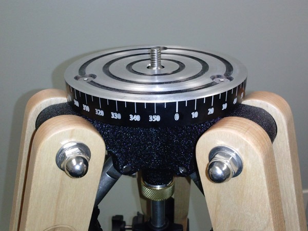 Narda-MITEQ’s TP-3W Tripod is a great option for those who require a reliable way to mount our horn antennas. These durable and weather-proof tripods have a standard ¼-20 camera mount. They are made out of Eastern Hard Rock Maple, a hard light-weight vibration damping wood, which optimizes stability. The wooden construction will also decrease any reflections on side lobes, since wood will not reflect any incoming or outgoing waves. The bracket supplied with the horn to be mounted makes it simple to change the elevation angle of the horn, while the ¼-20 mounting screw makes it easy to change the azimuth angle of the horn. All available Narda-MITEQ microwave horns may be mounted using our tripod. Please note: Bracket Option ( /BR ) must be specified when ordering horn antenna for tripod mounting. |
|||
| Model No. | Folded Height (in.) | Max. Height (in.) | Weight (lbs.) | |
| TP-3W | 40" | 62" | 11 | |