• Skip to main content
  • Skip to primary sidebar

Narda-ATM - Microwave RF Components Manufacturer

  • Home
  • Products
    • Coaxial Components
    • Ka-Band Satcom
    • Space Qualified
    • Waveguide Components
  • FAQ
    • Frequently Asked Questions
  • Ordering
    • Catalog
    • Credit Card Order Form
    • Ordering Information
    • Request A Quote
    • Sales Representatives
    • Terms And Conditions
  • Calculators
    • Cable Assy Loss Calculations
    • CF 100 Cable Loss
    • CF 135 Cable Loss
    • CF 160 Cable Loss
    • CF 210 Cable Loss
    • CF 300 Cable Loss
    • CF 500 Cable Loss
    • VSWR Calculator
    • Waveguide Gasket Selection
  • Photos
    • Coaxial Photos
    • Waveguide Photos
    • Flight Waveguide Photos
    • ATM Products In Use
  • Technical
    • Cable Assy Loss Calculation
    • Cable Length Tolerances
    • Mil-Spec References
    • Tech Notes
    • Waveguide Gasket Selection
    • Waveguide Flange Sizes & Types
    • Waveguide Info,Rectangular
    • Waveguide Gasket Info
    • Waveguide Info,Dbl Ridge
    • Waveguide Std. Tolerances
  • About ATM
    • Background
    • Contact ATM
    • News and Videos
    • Privacy Policy
    • Quality Control
    • Satisfaction Survey
You are here: Home / Coaxial Components / Phase Shifter / Line Stretcher

Phase Shifter / Line Stretcher

Coaxial Phase Shifter & Line Stretcher

Phase Shifters - 30°, 40°, 60°, 90°, 180°, 360°

ATM manufactures a wide variety of Phase Shifters / Line Stretchers to meet your design specifications. Three different models are available with a Standard Model requiring mechanical adjustment with a screwdriver/lock nut, Digital Counting Dial and a Direct Reading Option.

For more information please call us and discuss your phase shifter requirements with one of our design engineers.

ATM also manufactures a line of Motor Driven Phase Shifters for remotely changing phase in a variety of applications

Coaxial Phase Shifters:
SMA / Type-N Line Stretchers
Motor Driven Phase Shifters
Stepper Motor Driven Phase Shifter
Very Low Loss Phase Shifters

Waveguide:
Phase Shifters / Line Stretchers
High Power Phase Shifters

Ka-Band:
Coax Line Stretchers
Coaxial Phase Shifters
Waveguide Phase Shifters

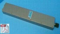
30°/GHz Phase Shifter - Series P140 & P240
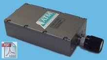
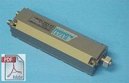
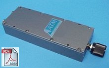
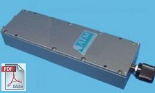
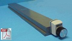
30°/GHz Phase Shifter - Series P140 & P240 - Standard Model

Standard Model phaseshifter has mechanical  adjustment with screwdriver shaft and locknut.

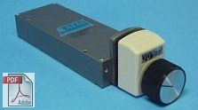
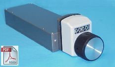
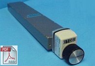
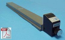
30°/GHz Phase Shifter - Series P140 & P240 - Digital Counting Dial Option

For Digital Counting Dial Option add "D" suffix to the Model Number
Example P/N: P1403 becomes: P1404D

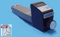
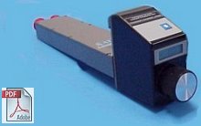
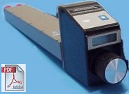
30°/GHz Phase Shifters - Series P140 & P240 - Direct Reading Option

For Direct Reading Option add "DRE" suffix to the Model Number
Example P/N: P1403 becomes: P1404DRE

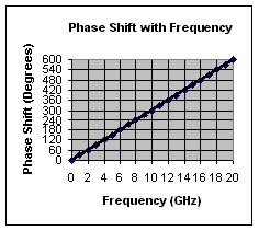
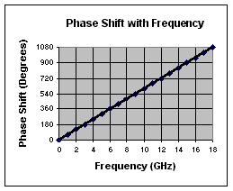
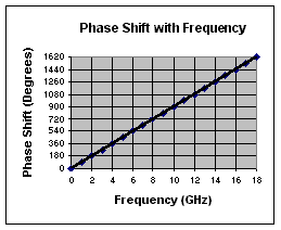
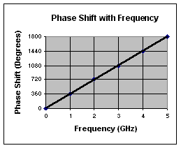
Phase Shift With Frequency Chart
30°/GHz PHASESHIFTERS
GENERAL SPECIFICATIONS ( All Options )
Electrical
RF Power: 100W average, 3kW peak
RF Connectors: SMA / Type-N, standard
Min. Adjustable Phase shift: 0 to 30°/GHz
+/- 0.35°/GHz Dial Accuracy for DRE Models    
Adjustable Group Delay min: 0 to 0.085 ns
Insertion Phase @ 1.0 GHz: 240° (min setting)
Settable: To better than 1.0 deg due to multi-turn shaft and linear control. One rotation at 1.0GHz is appox 3.5°
Temperature Stability:   0.025°/DC°/GHz
Mechanical
Size: 3.75" x 2.0" x 1.0"
Body: Aluminum
Connectors: Stainless Steel
Control: 0.25” dia. multi-turn Non-translating shaft, with appox.  10 turns from min to max phase adjust

Finish: Unique corrosion resistant 316 stainless steel epoxy coating IAW MIL-F-14072 Color Dusty Grey
Applicable Mil-Specs
General:
Product Specific:


30° Phase Shifters - Wide Band Models
Model No.
(SMA)
Model No.
(Type N)
Freq (GHz) Min. Phase
Adjust
I.L.
dB max
VSWR
Max
P1403 P2403 DC - 2.3 0 - 30°/GHz 0.5 1.5
P1404 P2404 DC - 4.3 0 - 30°/GHz 0.5 1.5
P1405 P2405 DC - 8.2 0 - 30°/GHz 0.6 1.5
P1406 P2406 DC - 12.7 0 - 30°/GHz 0.7 1.5
P1407 P2407 DC - 18.6 0 - 30°/GHz 1.0 1.6
P1408 N/A DC - 26.5 0 - 30°/GHz 1.5 2.0
P1408-360 N/A 18.0 - 26.5 0° - 360° 1.5 1.8
P1409-360** N/A 18.0 - 40.0 0° - 360° 2.5 2.0
Motor Drive Option available for remote applications - click here for Outline Drawing
** This unit supplied with K (2.9mm) connectors only.
Note: 0 - 30°/GHz Models achieve 30° minimum of phase shift @ 1GHz, actual phase shift varies linearly, corresponding to the Frequency unit is operating at.
Example:
If operated @ 2GHz, the unit can achieve 60° phase shift min.,
If operated @ 4GHz operation, the unit can achieve 120° phase shift min., and so on.
Use the "Phase Shift with Frequency" chart above for quick reference. 


40°/GHz Phase Shifter - Series P130 & P230

• Low profile phaseshifter

• Compact design for tight spaces

• Measures only: 4.0" x 1.25" x 1.0"

40°/GHz Phase Shifters - Series P130 & P230
Detailed Phase Shift with Frequency

 chart coming soon

40°/GHz PHASESHIFTERS
GENERAL SPECIFICATIONS
Electrical
RF Power: 100W average, 3kW peak
RF Connectors: SMA standard
Min. Adjustable Phase shift: 0 to 40°/GHz
+/- 0.35°/GHz Dial Accuracy for DRE Models
Adjustable Group Delay min: 0 to 0.112 ns
Insertion Phase @ 1.0 GHz:
Settable:
To better than 1.0 deg due to multi-turn shaft and linear control. One rotation at 1.0GHz is approx. 3.5°
Temperature Stability:
   0.025°/DC°/GHz
Mechanical
Size: 4.0" x 1.25" x .88"
Body: Aluminum
Connectors: Stainless Steel
Control: 0.25” dia. multi-turn Non-translating shaft, with approx.  13 turns from min to max phase adjust

Finish: Unique corrosion resistant 316 stainless steel epoxy coating IAW MIL-F-14072 Color Dusty Grey
Applicable Mil-Specs
General:
Product Specific:


40° Phase Shifters - Wide Band Models
Model No.
(SMA)
Freq. (GHz) Min Phase
Adjust
I.L.
dB max
VSWR
Max
P1303 DC - 2.3 0° - 40°/GHz 0.5 1.5
P1304 DC - 4.3 0° - 40°/GHz 0.5 1.5
P1305 DC - 8.2 0° - 40°/GHz 0.6 1.5
P1306 DC - 12.7 0° - 40°/GHz 0.7 1.5
P1307 DC - 18.6 0° - 40°/GHz 1.0 1.6
P1308 18.0 - 26.5 0° - 40° 1.5 2.0
Note: 0 - 40°/GHz Models achieve 40° minimum of phase shift @ 1GHz, actual phase shift varies linearly, corresponding to the Frequency unit is operating at.
Example: 
If operated @ 2GHz, the unit can achieve 80° phase shift min.,
If operated @ 4GHz operation, the unit can achieve 160° phase shift min., and so on.


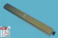
60°/GHz Phase Shifter - Series P150 & P250
60°/GHz Phase Shifters - Series P150 & P250 - Standard Model

Standard Model phaseshifter has mechanical  adjustment with screwdriver shaft and locknut.

60°/GHz Phase Shifters - Series P150 & P250 - Digital Counting Dial Option

For Digital Counting Dial Option add "D" suffix to the Model Number
Example P/N: P1503 becomes: P1503D

60°/GHz Phase Shifters - Series P150 & P250 - Direct Reading Option

For Direct Reading Option add "DRE" suffix to the Model Number
Example P/N: P1503 becomes: P1503DRE

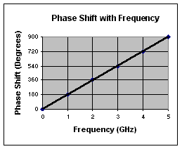
60°/GHz Phase Shifters - Series P150 & P250 - Phase Shift Chart
60°/GHz PHASESHIFTERS
GENERAL SPECIFICATIONS ( All Options )
Electrical
RF Power: 100W average, 3kW peak
RF Connectors: SMA/Type-N, standard
Min. Adjustable Phase shift: 0 to 60°/GHz
+/- 0.35°/GHz Dial Accuracy for DRE Models
Adjustable Group Delay min: 0 to 0.169 ns
Insertion Phase @ 1.0 GHz: 320° (min. setting)
Settable: To better than 1.0 deg due to multi-turn shaft and linear control. One rotation at 1.0GHz is approx. 3.5°
Temperature Stability:   0.025°/DC°/GHz
Mechanical
Size: 5.5" x 2.0" x 1.0"
Body: Aluminum
Connectors: Stainless Steel
Control: 0.25” dia. multi-turn Non-translating shaft, with approx.  18 turns from min to max phase adjust

Finish: Unique corrosion resistant 316 stainless steel epoxy coating IAW MIL-F-14072 Color Dusty Grey
Applicable Mil-Specs
General:
Product Specific:


60° Phase Shifters - Wide Band Models
Model No.
(SMA)
Model No.
(Type N)
Freq (GHz) Min Phase
Adjust
I.L.
dB max
VSWR
Max
P1503 P2503 DC - 2.3 0 - 60°/GHz 0.5 1.5
P1504 P2504 DC - 4.3 0 - 60°/GHz 0.5 1.5
P1505 P2505 DC - 8.2 0 - 60°/GHz 0.6 1.5
P1506 P2506 DC - 12.7 0 - 60°/GHz 0.7 1.5
P1507 P2507 DC - 18.6 0 - 60°/GHz 1.0 1.6
P1508 N/A 18.0 - 26.0 0 - 60° 1.5 2.0
Motor Drive Option available for remote applications - click here for Outline Drawing
Note: 0 - 60°/GHz Models achieve 60° minimum of phase shift @ 1GHz, actual phase shift varies linearly, corresponding to the Frequency unit is operating at.
Example:
If operated @ 2GHz, the unit can achieve 120° phase shift min.,
If operated @ 4GHz operation, the unit can achieve 240° phase shift min., and so on.
Use the "Phase Shift with Frequency" chart above for quick reference.


60° Phase Shifters - Special Band Models
Model No.
(SMA)
Model No.
(Type N)
Freq (GHz) Min Phase
Adjust
I.L.
dB max
VSWR
Max
P150C-180 P250C-180 5.85 - 6.5 0° - 180° 0.6 1.5
P150C-360 P250C-360 5.85 - 6.5 0° - 360° 0.6 1.5
P150X-180 P250X-180 7.9 - 8.4 0° - 180° 0.7 1.5
P150X-360 P250X-360 7.9 - 8.4 0° - 360° 0.7 1.5
P150K-180 P250K-180 12.7 - 14.5 0° - 180° 1.0 1.6
P150K-360 P250K-360 12.7 - 14.5 0° - 360° 1.0 1.6
P150K1-360 P250K1-360 17.0 - 18.2 0° - 360° 1.0 1.6
P150CK-180 P250CK-180 5.85 - 14.5 0° - 180° ** **
P150CK-360 P250CK-360 5.85 - 14.5 0° - 360° ** **
Motor Drive Option available for remote applications - click here for Outline Drawing
** These Models operate over a Tri-Band.  From 5.85 -6.5 GHz unit specs the same as P150C-, from
7.9-8.4 GHz unit specs the same as P150X-, and from 14.0-14.5 unit specs the same as P150K–


90°/GHz Phase Shifter - Series P160 & P260
90°/GHz Phase Shifters - Series P160 & P260 - Standard Model

Standard Model phaseshifter has mechanical  adjustment with screwdriver shaft and locknut.

90°/GHz Phase Shifters - Series P160 & P260 Digital Counting Dial Option

For Digital Counting Dial Option add "D" suffix to the Model Number
Example P/N: P1603 becomes: P1603D

90°/GHz Phase Shifters - Series P160 & P260 Direct Reading Option

For Direct Reading Option add "DRE" suffix to the Model Number
Example P/N: P1603 becomes: P1603DRE

90°/GHz Phase Shifters - Series P160 & P260 - Phase Shift Chart
90°/GHz PHASESHIFTERS
GENERAL SPECIFICATIONS ( All Options )
Electrical
RF Power: 100W average, 3kW peak
RF Connectors: SMA/Type-N, standard
Min. Adjustable Phase shift: 0 to 90°/GHz
+/- 0.35°/GHz Dial Accuracy for DRE Models
Adjustable Group Delay min: 0 to 0.254 ns
Insertion Phase @ 1.0 GHz:
Settable:
To better than 1.0 deg due to multi-turn shaft and linear control. One rotation at 1.0GHz is approx. 3.5°
Temperature Stability:
   0.025°/DC°/GHz
Mechanical
Size: 7.0" x 2.0" x 1.0"
Body: Aluminum
Connectors: Stainless Steel
Control: 0.25” dia. multi-turn Non-translating shaft, with approx.  27 turns from min to max phase adjust

Finish: Unique corrosion resistant 316 stainless steel epoxy coating IAW MIL-F-14072 Color Dusty Grey
Applicable Mil-Specs
General:
Product Specific:


90°/GHz Phase Shifters -  Wide Band Models
Model No.
(SMA)
Model No.
(Type N)
Freq (GHz) Min Phase
Adjust
I.L.
dB max
VSWR
Max
P1603 P2603 DC - 2.3 0 - 90°/GHz 0.5 1.3
P1604 P2604 DC - 4.3 0 - 90°/GHz 0.5 1.3
P1605 P2605 DC - 8.2 0 - 90°/GHz 0.6 1.4
P1606 P2606 DC - 12.7 0 - 90°/GHz 0.7 1.5
P1607 P2607 DC - 18.6 0 - 90°/GHz 1.0 1.6
P1608 N/A DC - 26.5 0 - 90°/GHz 1.7 2.0
Motor Drive Option available for remote applications - click here for Outline Drawing
Note: 0 - 90°/GHz Models achieve 90° minimum of phase shift @ 1GHz, actual phase shift varies linearly, corresponding to the Frequency unit is operating at.
Example:
If operated @ 2GHz, the unit can achieve 180° phase shift min.,
If operated @ 4GHz operation, the unit can achieve 360° phase shift min., and so on.
Use the "Phase Shift with Frequency" chart above for quick reference.


180°/GHz Phase Shifter - Series P120 & P220
180°/GHz Phase Shifters - Series P120 & P220 Standard Model

Standard Model phaseshifter has mechanical  adjustment with screwdriver shaft  and locknut.

90°/GHz Phase Shifters - Series P160 & P260 Digital Counting Dial Option

For Digital Counting Dial Option add "D" suffix to the Model Number
Example P/N: P1213 becomes: P1213D

90°/GHz Phase Shifters - Series P160 & P260 Direct Reading Option

For Direct Reading Option add "DRE" suffix to the Model Number
Example P/N: P1213 becomes: P1213DRE

180°/GHz Phase Shifters - Series P120 & P220 - Phase Shift Chart
180°/GHz PHASESHIFTERS
GENERAL SPECIFICATIONS ( All Options )
Electrical
RF Power: 100W average, 3kW peak
RF Connectors: SMA/Type-N, standard
Min. Adjustable Phase shift: 0 to 180°/GHz
+/- 0.35°/GHz Dial Accuracy for DRE Models
Adjustable Group Delay min: 0 to 0.508 ns
Insertion Phase @ 1.0 GHz: 760° (min. setting)
Settable: To better than 1.0 deg due to multi-turn shaft and linear control. One rotation at 1.0GHz is approx. 3.5°
Temperature Stability:   0.025°/DC°/GHz
Mechanical
Size: 12.0" x 2.0" x 1.0"
Body: Aluminum
Connectors: Stainless Steel
Control: 0.25” dia. multi-turn Non-translating shaft, with approx.  54 turns from min to max phase adjust

Finish: Unique corrosion resistant 316 stainless steel epoxy coating IAW MIL-F-14072 Color Dusty Grey
Applicable Mil-Specs
General:
Product Specific:


180°/GHz Phase Shifters -  Wide Band Models
Model No.
(SMA)
Model No.
(Type N)
Freq GHz Min Phase
Adjust
I.L.
dB max
VSWR
Max
P1213 P2213 DC - 2.3 0 - 180°/GHz 0.6 1.3
P1214 P2214 DC - 4.3 0 - 180°/GHz 0.7 1.5
Motor Drive Option available for remote applications - click here for Outline Drawing
Note: 0 - 180°/GHz Models achieve 180° minimum of phase shift @ 1GHz, actual phase shift varies linearly, corresponding to the Frequency unit is operating at.
Example:
If operated @ 2GHz, the unit can achieve 360° phase shift min,
If operated @ 4GHz operation, the unit can achieve 720° phase shift min., and so on.
Use the "Phase Shift with Frequency" chart above for quick reference.


360°/GHz Phase Shifter - Series P1100 & P2100
360°/GHz Phase Shifters - Series P1100 & P2100 Standard Model

Standard Model has mechanical  adjustment with screwdriver shaft  and locknut.

360°/GHz Phase Shifters - Series P1100 & P2100 Digital Counting Dial Option

For Digital Counting Dial Option add "D" suffix to the Model Number
Example P/N: P1102 becomes: P1102D

360°/GHz Phase Shifters - Series P1100 & P2100 Direct Reading Option

For Direct Reading Option add "DRE" suffix to the Model Number
Example P/N: P1102 becomes: P1102DRE

360°/GHz Phase Shifters - Series P1100 & P2100 Phase Shift Chart
360°/GHz PHASESHIFTERS
GENERAL SPECIFICATIONS ( All Options )

Electrical
RF Power: 100W average, 3kW peak
RF Connectors: SMA/Type-N, standard
Min. Adjustable Phase shift: 0 to 360°/GHz
+/- 0.35°/GHz Dial Accuracy for DRE Models
Adjustable Group Delay min: 0 to 1.016 ns
Insertion Phase @ 1.0 GHz: 1375° (min setting)
Settable: To better than 1.0 deg due to multi-turn shaft and linear control. One rotation at 1.0GHz is approx. 3.5°
Temperature Stability: 0.025°/DC°/GHz

Mechanical
Size: 24.0" x 3.0" x 1.2"
Body: Aluminum
Connectors: Stainless Steel
Control: 0.25” dia. multi-turn Non-translating shaft, with approx.  100 turns from min to max phase adjust

Finish: Unique corrosion resistant 316 stainless steel epoxy coating IAW MIL-F-14072 Color Dusty Grey
Applicable Mil-Specs
General:
Product Specific:


360°/GHz Phase Shifters -  Wide Band Models
Model No.
(SMA)
Model No.
(Type N)
Freq GHz Min Phase
Adjust
I.L.
dB max
VSWR
Max / Typical
P1102 P2102 DC - 1.0 360°/GHz 0.5 1.3 / 1.25
P1103 P2103 DC - 2.5 360°/GHz 0.8 1.5 / 1.25
Motor Drive Option available for remote applications - click here for Outline Drawing
Note: 0 - 360°/GHz Models achieve 360° minimum of phase shift @ 1GHz, actual phase shift varies linearly, corresponding to the Frequency unit is operating at.
Example:
If operated @ 2GHz, the unit can achieve 720° phase shift min.
Use the "Phase Shift with Frequency" chart above for quick reference.


Primary Sidebar

Search for:

Components Menu

›   Coaxial Components
›   Ka-Band Satcom Components
›   Space Qualified Components
›   Waveguide Components

Latest News and Videos

  • Narda-ATM Re-Certified By NQA for ISO-9001:2015

  • Home
  • Coaxial Components
  • Waveguide Components
  • Ka-Band Components
  • Space Qualified Components

Copyright © 2023 · Narda-ATM