• Skip to main content
  • Skip to primary sidebar

Narda-ATM - Microwave RF Components Manufacturer

  • Home
  • Products
    • Coaxial Components
    • Ka-Band Satcom
    • Space Qualified
    • Waveguide Components
  • FAQ
    • Frequently Asked Questions
  • Ordering
    • Catalog
    • Credit Card Order Form
    • Ordering Information
    • Request A Quote
    • Sales Representatives
    • Terms And Conditions
  • Calculators
    • Cable Assy Loss Calculations
    • CF 100 Cable Loss
    • CF 135 Cable Loss
    • CF 160 Cable Loss
    • CF 210 Cable Loss
    • CF 300 Cable Loss
    • CF 500 Cable Loss
    • VSWR Calculator
    • Waveguide Gasket Selection
  • Photos
    • Coaxial Photos
    • Waveguide Photos
    • Flight Waveguide Photos
    • ATM Products In Use
  • Technical
    • Cable Assy Loss Calculation
    • Cable Length Tolerances
    • Mil-Spec References
    • Tech Notes
    • Waveguide Gasket Selection
    • Waveguide Flange Sizes & Types
    • Waveguide Info,Rectangular
    • Waveguide Gasket Info
    • Waveguide Info,Dbl Ridge
    • Waveguide Std. Tolerances
  • About ATM
    • Background
    • Contact ATM
    • News and Videos
    • Privacy Policy
    • Quality Control
    • Satisfaction Survey
You are here: Home / Coaxial Components / Phase Shifter Motor Driven

Phase Shifter Motor Driven

Motor Driven Coaxial Phase Shifters

DC Motor Drives For Phase Shifters

ATM manufactures a variety of DC motor drives for phase shifters that allow phase changes to be performed remotely. 

Our complete phase shifter line includes phaseshifters with 30, 40, 60, 90, 180 and 360 degree phase shift with standard mechanical adjustments, digital counting dials and direct reading dials.

Any of ATM's phase shifters can be used with the motor drive modules on this page.

For more information on phase shifters or DC driven phase shifters, please call us and discuss your needs with one of our design engineers.

Coaxial Phase Shifters:
SMA / Type-N Line Stretchers
Coaxial Phase Shifters
Stepper Motor Driven Phase Shifter
Very Low Loss Phase Shifters

Waveguide:
WG Phase Shifters / Line Stretchers
WG High Power Phase Shifters

Ka-Band:
Ka-Band Coax Line Stretchers
Ka-Band Coaxial Phase Shifters
Ka-Band Waveguide Phase Shifters

Motor Driven Phase Shifters
Motor Driven P150 Phase Shifter

 P150 Phase Shifter mounted to Motor Drive

GENERAL SPECIFICATIONS
( MOTOR DRIVE UNIT ONLY)
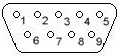
Electrical
Motor Drive Connector: 9-Pin D-Sub (male)
Voltage: 18-30VDC
Max. Amperage: 250mA & 600mA starting
Mechanical
Body: Aluminum Construction
Operating Temp:
Finish: Unique corrosion resistant 316 stainless steel epoxy coating IAW MIL-F-14072 Color Dusty Grey
  • ATM's motor driven phase shifters utilize DC motors with integrated, long life gear reductions ideal for High Reliability applications.
  • The unit will operate with a set DC voltage between 18-30VDC, commonly found in most systems or by a separate DC power supply. Motor speed will vary based on Voltage used. Maximum running current is 250mA & 600mA max starting.
  • To prevent motor damage, micro switches are used to stop the motor at the minimum and maximum travel positions
  • Units are provided with a 9 pin D Sub Male connector allowing for control voltage, end point indication if desired, and follower potentiometer. See connector pin-out details.
  • These devices are best controlled by an external Double-Pole/Double-Throw (DPDT) switch or for better control use the optional ATM External Control Module.
  • Any one of ATM's Phase Shifters can be mounted to a motor drive.


Interface - Motor Driven Phase Shifters

1. Motor Control Voltage
Pins 2 and 7 of the nine pin D Sub male connector will have fixed DC voltage between 18-30 volts applied.  To increase phase pin 2 is (+) and pin 7 is (-).  To reverse the direction 2 is (-) and 7 is (+).  In both directions a stop is provided by means of Micro switches.

2. End Point Indicator *
The switch is also used to provide end point indication by means of pins 1 and 6 developing a voltage when the device has reached the maximum limit, (for 2+ and 7-). Pins will 3 and 8 will develop a voltage when a minimum limit is met. (for 2- and 7+). The developing voltage is equal to supply voltage used.

3. Follower Potentiometer **
A 10K Pot with an output proportional to the position of the motor drive mechanism is available at pins 4, 5, and 9.

MOTOR SPEED / RESPONSE TIME
ATM MODEL # DEG/GHz CASE LENGTH TIME*
P140/P240 30° 3.75" 30 sec.
P150/P250 60° 5.50" 14 sec.
P160/P260 90° 7.0" 20 sec.
P1210/P2210 180° 12.0" 40 sec.
P1100/P2100 360° 24.0" 30 sec.

 * Approximate time to drive the phase shifter from min to max. for given model, ( using sufficient voltage).

CONNECTOR PIN OUT

Pin Out Configuration

Pin # Function
+ 2 Increase Phase
- 7
- 2 Decrease Phase
+ 7
+ 1 * End Point Indicator
(Max. Phase)
   6
- 3 * End Point Indicator
(Min. Phase)
   8
** 10K Follower Potentiometer
4 Pot End Points
9
5 Wiper


Standard Models - Motor Driven Phase Shifters
Basic Phaseshifter
Type
Generic* Model
No. (SMA)
Outline Dwg.
30°/GHz P14XX-28 Dwg
60°/GHz P15XX-28 Dwg
90°/GHz P16XX-28 Dwg
180°/GHz P121X-28 Dwg
360°/GHz P11XX-28 Dwg
* When ordering a Motor Driven Phase Shifter, you will need to create the actual model number, based on the specific phase shifter of you choosing by adding the suffix -28 at the end of the model number.
See our Phase Shifter page to find the  30°, 60°, 90°, 180°, or 360° model you wish to start with.
Example:   P/N P1604 becomes P1604-28 when ordering as a motor driven unit.
Any one of ATM's Phase Shifters can be mounted to a motor drive.


Optional External Control Module
An External Drive Control Module, part number MCM-001 shown at right, is available for the motor drive as an optional accessory. It includes:
 
1.  Crisp tactile switches to control drive.
2.  Max/Min position indicator lights.
3.  Follower potentiometer terminals.
4.  Self-switching power supply with input of 120 VAC - 240VAC.*     
5.  6 Ft, 9 pin cable to interconnect the control box to the motor driven device.  

*If supplied power source is not used, an input of 18-30 VDC through the 9 pin connector may be substituted.

Motor Drive External Control Module for Phase Shifters


Primary Sidebar

Search for:

Components Menu

›   Coaxial Components
›   Ka-Band Satcom Components
›   Space Qualified Components
›   Waveguide Components

Latest News and Videos

  • Narda-ATM Re-Certified By NQA for ISO-9001:2015

  • Home
  • Coaxial Components
  • Waveguide Components
  • Ka-Band Components
  • Space Qualified Components

Copyright © 2023 · Narda-ATM