High Power Directional Couplers For Coaxial RF |
|---|
High Power Broadband Directional Couplers
Narda-MITEQ manufactures High Power, Broadband Sampling, Coaxial Single and Dual Directional Couplers. Our RF coax couplers offer both octave band and multi-band for high power applications from 200W to 1400 watts.
Narda-MITEQ also manufactures a full line of Standard Coaxial Directional Couplers, 3dB Hybrid Couplers, and 90 degree Hybrid Couplers.
For more information on our full line of high power directional couplers feel free to call us and discuss your needs with one of our design engineers.
| Octave & Multi-Band, SMA - 200 Watt High Power Directional Couplers | |
|---|---|
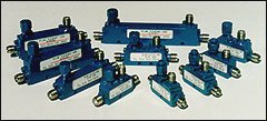 |
Electrical |
| Freq (GHz) | Coupling (dB) |
Freq Sens (+/- dB) |
Direc. (dB min) |
Ins. Loss (dB) | VSWR max | Model No | Outline Dwg. |
||
| Excluding Coupling |
True | Main | Sec. | ||||||
| 0.5 - 1.0 | 10+/-1.25 20+/-1.25 30+/-1.25 |
0.75 | 25 | 0.20 0.15 0.15 |
0.80 0.20 0.20 |
1.10 | 1.10 | CH112-10 CH112-20 CH112-30 |
Fig 1 Fig 1 Fig 2 |
| 1.0 - 2.0 | 10+/-1.25 20+/-1.25 30+/-1.25 |
0.75 | 25 | 0.20 0.15 0.15 |
0.80 0.20 0.20 |
1.10 | 1.10 | CH113-10 CH113-20 CH113-30 |
Fig 3 Fig 3 Fig 4 |
| 2.0 - 4.0 | 10+/-1.25 20+/-1.25 30+/-1.25 |
0.75 | 22 | 0.20 0.15 0.15 |
0.80 0.20 0.20 |
1.15 | 1.15 | CH114-10 CH114-20 CH114-30 |
Fig 5 Fig 5 Fig 6 |
| 2.6 - 5.2 | 10+/-1.25 20+/-1.25 30+/-1.25 |
0.75 | 20 | 0.20 | 0.80 0.25 0.20 |
1.25 | 1.25 | CH114F-10 CH114F-20 CH114F-30 |
Fig 7 Fig 7 Fig 8 |
| 4.0 - 8.0 | 20+/-1.25 30+/-1.25 |
0.75 | 15 | 0.25 | 0.30 0.25 |
1.25 | 1.30 | CH115-20 CH115-30 |
Dwg |
| 4.0 - 18.0 | 35+/-1.50 | 1.00 | 12 | 0.5 | 0.50 | 1.40 | 1.35 | CH125H-35* | Dwg |
|
*200 watt dual directional coupler readily available (specs the same as directional coupler) |
|||||||||
| Octave Band, Type-N - 200 Watt High Power Directional Couplers | |
|---|---|
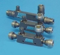 |
Electrical |
| Freq (GHz) | Coupling (dB) |
Freq. Sens. (+/- dB) |
Direc. (dB min) |
Ins. Loss (dB | VSWR max | Model No | Outline Dwg. |
||
| Excluding Coupling |
True | Main | Sec | ||||||
| 0.5 - 1.0 | 10+/-1.25 20+/-1.25 30+/-1.25 |
0.75 | 25 | 0.20 0.15 0.15 |
0.80 0.20 0.20 |
1.20 | 1.20 | CH212-10 CH212-20 CH212-30 |
Fig 1 Fig 1 Fig 2 |
| 1.0 - 2.0 | 10+/-1.25 20+/-1.25 30+/-1.25 |
0.75 | 25 | 0.20 0.15 0.15 |
0.80 0.20 0.20 |
1.20 | 1.20 | CH213-10 CH213-20 CH213-30 |
Fig 3 Fig 3 Fig 3 |
| 2.0 - 4.0 | 10+/-1.25 20+/-1.25 30+/-1.25 |
0.75 | 22 | 0.20 0.15 0.15 |
0.80 0.20 0.20 |
1.25 | 1.25 | CH214-10 CH214-20 CH214-30 |
Fig 6 Fig 6 Fig 7 |
| 2.6 - 5.2 | 10+/-1.25 20+/-1.25 30+/-1.25 |
0.75 | 20 | 0.20 | 0.80 0.25 0.20 |
1.35 | 1.35 | CH214F-10 CH214F-20 CH214F-30 |
Fig 5 Fig 5 Fig 5 |
| 4.0 - 8.0 | 20+/-1.25 30+/-1.25 |
0.75 | 15 | 0.25 | 0.30 0.25 |
1.30 | 1.35 | CH215-20 CH215-30 |
Dwg |
| 4.0 - 18.0 | 35+/-1.50 | 1.00 | 12 | 0.5 | 0.50 | 1.45 | 1.40 | CH225H-35* | Dwg |
|
* 200 watt dual directional coupler readily available (specs the same as directional coupler). |
|||||||||
| 600 Watt High Power Directional Couplers | |
|---|---|
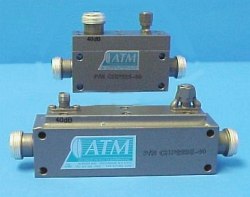 |
Electrical |
| Freq (GHz) | Coupling (dB) |
Freq Sens (+/- dB) |
Dir. (dB min) |
Ins. Loss (dB) | VSWR max.* | Model No | Outline Dwg. |
||
| Excluding Coupling |
True | Main | Sec | ||||||
| 0.50 - 1.0 | 30+/-0.5 40+/-0.5 50+/-0.5 |
1.2 | 20 | 0.15 0.15 0.15 |
0.20 0.20 0.20 |
1.20 | 1.30 | CHP222-30 CHP222-40 CHP222-50 |
Dwg |
| 0.50 - 2.0 | 30+/-0.5 40+/-0.5 50+/-0.5 |
1.2 | 18 | 0.15 0.15 0.15 |
0.20 0.20 0.20 |
1.20 | 1.20 | CHP222D-30 CHP222D-40 CHP222D-50 |
Dwg |
| 0.86 - 1.7 | 30+/-0.5 40+/-0.5 50+/-0.5 |
1.0 | 23 | 0.15 0.15 0.15 |
0.20 0.20 0.20 |
1.20 | 1.30 | CHP223L-30 CHP223L-40 CHP223L-50 |
Dwg |
| 1.0 - 2.0 | 30+/-0.5 40+/-0.5 50+/-0.5 |
0.8 | 23 | 0.15 0.15 0.15 |
0.20 0.20 0.20 |
1.20 | 1.30 | CHP223-30 CHP223-40 CHP223-50 |
Dwg |
| 2.0 - 4.0 | 30+/-0.5 40+/-0.5 50+/-0.5 |
0.8 | 23 | 0.15 0.15 0.15 |
0.20 0.20 0.20 |
1.25 | 1.30 | CHP224-30 CHP224-40 CHP224-50 |
Dwg |
| 4.0 - 8.0 | 30+/-0.5 40+/-0.5 50+/-0.5 |
0.8 | 17 | 0.15 0.15 0.15 |
0.20 0.20 0.20 |
1.25 | 1.35 | CHP225-30 CHP225-40 CHP225-50 |
Dwg |
| 1.0 - 4.0 | 30+/-0.5 40+/-0.5 50+/-0.5 |
0.8 | 22 | 0.15 0.15 0.15 |
0.20 0.20 0.20 |
1.20 | 1.30 | CHP223E-30 CHP223E-40 CHP223E-50 |
Dwg |
| 0.8 - 4.2 | 40+/-0.5 50+/-0.5 |
1.3 | 20 | 0.15 0.15 |
0.20 0.20 |
1.20 | 1.30 | CHP222L-40 CHP222L-50 |
Dwg |
| 2.0 - 8.0 | 30+/-0.5 40+/-0.5 50+/-0.5 |
1.0 | 17 | 0.15 0.15 0.15 |
0.20 0.20 0.20 |
1.25 | 1.35 | CHP224F-30 CHP224F-40 CHP224F-50 |
Dwg |
|
* Type-N Models are spec .05 higher in VSWR than SMA models |
|||||||||
| 600 Watt High Power Dual Directional Couplers | |
|---|---|
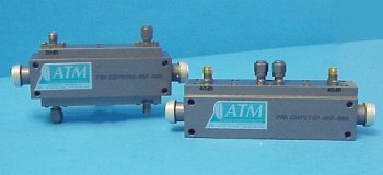 |
Electrical |
| Freq. (GHz) |
Coupling (dB) |
Freq. |
Dir. (dB min) |
Ins. Loss (dB) | VSWR max* | Model No** | Outline Dwg |
||
| Excluding Coupling |
True | Main | Sec | ||||||
| 0.50 - 1.0 | 30+/-1.00 40+/-1.00 50+/-1.00 |
1.2 | 20 | 0.15 0.15 0.15 |
0.20 0.20 0.20 |
1.20 | 1.30 | CHP272-30F-30R CHP272-40F-40R CHP272-50F-50R |
Dwg |
| 0.50 - 2.0 | 30+/-1.00 40+/-1.00 50+/-1.00 |
1.2 | 18 | 0.15 0.15 0.15 |
0.20 0.20 0.20 |
1.20 | 1.30 | CHP272D-30F-30R CHP272D-40F-40R CHP272D-50F-50R |
Dwg |
| 0.86 - 1.7 | 30+/-1.00 40+/-1.00 50+/-1.00 |
1.0 | 23 | 0.15 0.15 0.15 |
0.20 0.20 0.20 |
1.20 | 1.30 | CHP273L-30F-30R CHP273L-40F-40R CHP273L-50F-50R |
Dwg |
| 1.0 - 2.0 | 30+/-1.00 40+/-1.00 50+/-1.00 |
1.0 | 23 | 0.15 0.15 0.15 |
0.20 0.20 0.20 |
1.20 | 1.30 | CHP273-30F-30R CHP273-40F-40R CHP273-50F-50R |
Dwg |
| 2.0 - 4.0 | 30+/-1.00 40+/-1.00 50+/-1.00 |
1.0 | 23 | 0.15 0.15 0.15 |
0.20 0.20 0.20 |
1.25 | 1.30 | CHP274-30F-30R CHP274-40F-40R CHP274-50F-50R |
Dwg |
| 4.0 - 8.0 | 30+/-1.00 40+/-1.00 50+/-1.00 |
1.0 | 21 | 0.15 0.15 0.15 |
0.20 0.20 0.20 |
1.25 | 1.30 | CHP275-30F-30R CHP275-40F-40R CHP275-50F-50R |
Dwg |
| 1.0 - 4.0 | 30+/-1.00 40+/-1.00 50+/-1.00 |
1.0 | 22 | 0.15 0.15 0.15 |
0.20 0.20 0.20 |
1.20 | 1.30 | CHP273E-30F-30R CHP273E-40F-40R CHP273E-50F-50R |
Dwg |
| 0.8 - 4.2 | 40+/-1.00 50+/-1.00 |
1.3 | 20 | 0.15 | 0.20 | 1.20 | 1.30 | CHP272L-40F-40R CHP272L-50F-50R |
Dwg |
| 2.0 - 8.0 | 30+/-1.00 40+/-1.00 50+/-1.00 |
1.0 | 19 | 0.15 0.15 0.15 |
0.20 0.20 0.20 |
1.25 | 1.30 | CHP274F-30F-30R CHP274F-40F-40R CHP274F-50F-50R |
Dwg |
|
* Type-N Models are spec .05 higher in VSWR than SMA models |
|||||||||
|
** Standard model comes with one forward port and one reflected port. To mix the coupling values of each port change the end of the part number to desired coupling value as follows: |
|||||||||
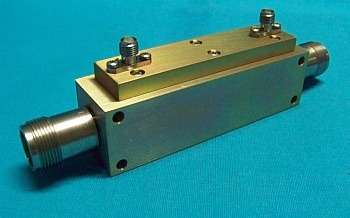
| 900 Watt High Power Directional Coupler - SC Type | |
|---|---|
 |
Electrical |
| Freq (GHz) | Coupling (dB) |
Freq Sens (+/- dB) |
Dir. (dB min) |
Ins. Loss (dB) | VSWR max. | Model No | Outline Dwg. |
||
| Excluding Coupling |
True | Main | Sec | ||||||
| 0.50 - 2.0 | 30+/-0.5 40+/-0.5 50+/-0.5 |
1.2 | 18 | 0.15 0.15 0.15 |
0.20 0.20 0.20 |
1.20 | 1.30 | CHPsc22D-30 CHPsc22D-40 CHPsc22D-50 |
|
| 0.86 - 1.7 | 30+/-0.5 40+/-0.5 50+/-0.5 |
0.8 | 23 | 0.15 0.15 0.15 |
0.20 0.20 0.20 |
1.20 | 1.30 | CHPsc23L-30 CHPsc23L-40 CHPsc23L-50 |
Dwg |
| 1.0 - 2.0 | 30+/-0.5 40+/-0.5 50+/-0.5 |
0.8 | 23 | 0.15 0.15 0.15 |
0.20 0.20 0.20 |
1.20 | 1.30 | CHPsc23-30 CHPsc23-40 CHPsc23-50 |
Dwg |
| 2.0 - 4.0 | 30+/-0.5 40+/-0.5 50+/-0.5 |
0.8 | 23 | 0.15 0.15 0.15 |
0.20 0.20 0.20 |
1.25 | 1.30 | CHPsc24-30 CHPsc24-40 CHPsc24-50 |
Dwg |
| 4.0 - 8.0 | 30+/-0.5 40+/-0.5 50+/-0.5 |
0.8 | 21 | 0.15 0.15 0.15 |
0.20 0.20 0.20 |
1.30 | 1.30 | CHPsc25-30 CHPsc25-40 CHPsc25-50 |
|
| 1.0 - 4.0 | 30+/-0.5 40+/-0.5 50+/-0.5 |
0.8 | 22 | 0.15 0.15 0.15 |
0.20 0.20 0.20 |
1.20 | 1.30 | CHPsc23E-30 CHPsc23E-40 CHPsc23E-50 |
Dwg |
| 0.8 - 4.2 | 40+/-0.5 50+/-0.5 |
1.3 | 20 | 0.15 0.15 |
0.20 0.20 |
1.20 | 1.30 | CHPsc22L-40 CHPsc22L-50 |
Dwg |
| 2.0 - 8.0 | 30+/-0.5 40+/-0.5 50+/-0.5 |
0.8 | 19 | 0.15 0.15 0.15 |
0.20 0.20 0.20 |
1.30 | 1.30 | CHPsc24F-30 CHPsc24F-40 CHPsc24F-50 |
|
| 900 Watt High Power Dual Directional Coupler - SC Type | |
|---|---|
 |
Electrical |
| Freq (GHz) |
Coupling (dB) |
Freq Sens. (+/- dB) |
Dir. (dB min) |
Ins. Loss (dB) | VSWR max. | Model No | Outline Dwg |
||
| Exclude Coup |
True | Main | Sec | ||||||
| 0.50 - 2.0 | 30+/-1.00 40+/-1.00 50+/-1.00 |
1.2 | 18 | 0.15 0.15 0.15 |
0.20 0.20 0.20 |
1.20 | 1.30 | CHPsc72D-30F-30R CHPsc72D-40F-40R CHPsc72D-50F-50R |
|
| 0.86 - 1.7 | 30+/-1.00 40+/-1.00 50+/-1.00 |
1.0 | 23 | 0.15 0.15 0.15 |
0.20 0.20 0.20 |
1.25 | 1.30 | CHPsc73L-30F-30R CHPsc73L-40F-40R CHPsc73L-50F-50R |
Dwg |
| 1.0 - 2.0 | 30+/-1.00 40+/-1.00 50+/-1.00 |
1.0 | 23 | 0.15 0.15 0.15 |
0.20 0.20 0.20 |
1.25 | 1.30 | CHPsc73-30F-30R CHPsc73-40F-40R CHPsc73-50F-50R |
Dwg |
| 2.0 - 4.0 | 30+/-1.00 40+/-1.00 50+/-1.00 |
1.0 | 23 | 0.15 0.15 0.15 |
0.20 0.20 0.20 |
1.30 | 1.30 | CHPsc74-30F-30R CHPsc74-40F-40R CHPsc74-50F-50R |
Dwg |
| 4.0 - 8.0 | 30+/-1.00 40+/-1.00 50+/-1.00 |
1.0 | 21 | 0.15 0.15 0.15 |
0.20 0.20 0.20 |
1.30 | 1.30 | CHPsc75-30F-30R CHPsc75-40F-40R CHPsc75-50F-50R |
Dwg |
| 1.0 - 4.0 | 30+/-1.00 40+/-1.00 50+/-1.00 |
1.0 | 22 | 0.15 0.15 0.15 |
0.20 0.20 0.20 |
1.25 | 1.30 | CHPsc73E-30F-30R CHPsc73E-40F-40R CHPsc73E-50F-50R |
Dwg |
| 0.8 - 4.2 | 40+/-1.00 50+/-1.00 |
1.3 | 20 | 0.15 0.15 |
0.20 0.20 |
1.25 | 1.30 | CHPsc72L-40F-40R CHPsc72L-50F-50R |
Dwg |
| 2.0 - 8.0 | 30+/-1.00 40+/-1.00 50+/-1.00 |
1.0 | 19 | 0.15 0.15 0.15 |
0.20 0.20 0.20 |
1.30 | 1.30 | CHPsc74F-30F-30R CHPsc74F-40F-40R CHPsc74F-50F-50R |
Dwg |
|
Dwg*Standard model comes with one forward port and one reflected port. To mix the coupling values of each port change the end of the part number to desired coupling value as follows: Ex: CHPsc73L-30F-30R = CHPsc73L-30F-40R In this example a 30dB forward port remains the same, while a 30dB reflected port was changed to a 40dB reflected port. |
|||||||||
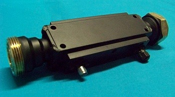
| 900 Watt & 1400 Watt High Power Single Directional Coupler - 7/16 Type | |
|---|---|
 |
Electrical |
| Freq (GHz) | Coup (dB) +/- 0.5 |
Freq Sens (+/- dB) |
Dir. (dB min) |
Ins. Loss (dB)* | VSWR max. |
Model No |
Model No 1400 Watts |
Dwg | ||
| Excl Coup |
True | Main | Sec | |||||||
| 0.50-2.0 | 30 40 50 |
1.2 | 18 | 0.15 0.15 0.15 |
0.20 0.20 0.20 |
1.20 | 1.30 | CHP(7/16)22D-30 CHP(7/16)22D-40 CHP(7/16)22D-50 |
CHP(7/16)22D-1400-30 CHP(7/16)22D-1400-40 CHP(7/16)22D-1400-50 |
|
| 0.86-1.7 | 30 40 50 |
0.8 | 23 | 0.15 0.15 0.15 |
0.20 0.20 0.20 |
1.35 | 1.30 | CHP(7/16)23L-30 CHP(7/16)23L-40 CHP(7/16)23L-50 |
CHP(7/16)23L-1400-30 CHP(7/16)23L-1400-40 CHP(7/16)23L-1400-50 |
Dwg |
| 1.0-2.0 | 30 40 50 |
0.8 | 23 | 0.15 0.15 0.15 |
0.20 0.20 0.20 |
1.35 | 1.30 | CHP(7/16)23-30 CHP(7/16)23-40 CHP(7/16)23-50 |
CHP(7/16)23-1400-30 CHP(7/16)23-1400-40 CHP(7/16)23-1400-50 |
Dwg |
| 2.0-4.0 | 30 40 50 |
0.8 | 23 | 0.15 0.15 0.15 |
0.20 0.20 0.20 |
1.40 | 1.30 | CHP(7/16)24-30 CHP(7/16)24-40 CHP(7/16)24-50 |
CHP(7/16)24-1400-30 CHP(7/16)24-1400-40 CHP(7/16)24-1400-50 |
Dwg |
| 4.0-8.0 | 30 40 50 |
0.8 | 21 | 0.15 0.15 0.15 |
0.20 0.20 0.20 |
1.40 | 1.30 | CHP(7/16)25-30 CHP(7/16)25-40 CHP(7/16)25-50 |
CHP(7/16)25-1400-30 CHP(7/16)25-1400-40 CHP(7/16)25-1400-50 |
|
| 1.0-4.0 | 30 40 50 |
0.8 | 22 | 0.15 0.15 0.15 |
0.20 0.20 0.20 |
1.35 | 1.30 | CHP(7/16)23E-30 CHP(7/16)23E-40 CHP(7/16)23E-50 |
CHP(7/16)23E-1400-30 CHP(7/16)23E-1400-40 CHP(7/16)23E-1400-50 |
Dwg |
| 0.8-4.2 | 40 50 |
1.3 | 20 | 0.15 0.15 |
0.20 0.20 |
1.35 | 1.30 | CHP(7/16)22L-40 CHP(7/16)22L-50 |
CHP(7/16)22L-1400-40 CHP(7/16)22L-1400-50 |
Dwg |
| 2.0-8.0 | 30 40 50 |
0.8 | 19 | 0.15 0.15 0.15 |
0.20 0.20 0.20 |
1.40 | 1.30 | CHP(7/16)24F-30 CHP(7/16)24F-40 CHP(7/16)24F-50 |
CHP(7/16)24F-1400-30 CHP(7/16)24F-1400-40 CHP(7/16)24F-1400-50 |
|
| * Due to the 7/16 connector I.L is 0.2dB up to 5.5GHz and 0.6 dB above. All other specs remain the same |
||||||||||
| 900 Watt & 1400 Watt High Power Dual Directional Coupler - 7/16 Type | |
|---|---|
 |
Electrical |
| Freq. (GHz) |
Coup dB +/- 1.00 |
Frq Sns +/- dB |
Dir dB min |
Ins. Loss (dB)* |
VSWR max. |
Model No 900 Watts |
Model No 1400 Watts |
Dwg | ||
| Excl Coup |
True | Mn. | Sec | |||||||
| 0.50 -2.0 |
30 40 50 |
1.2 | 18 | 0.15 0.15 0.15 |
0.20 0.20 0.20 |
1.20 | 1.30 | CHP(7/16)72D-30F-30R CHP(7/16)72D-40F-40R CHP(7/16)72D-50F-50R |
CHP(7/16)72D-1400-30F-30R CHP(7/16)72D-1400-40F-40R CHP(7/16)72D-1400-50F-50R |
|
| 0.86 -1.7 |
30 40 50 |
1.0 | 23 | 0.15 0.15 0.15 |
0.20 0.20 0.20 |
1.35 | 1.30 | CHP(7/16)73L-30F-30R CHP(7/16)73L-40F-40R CHP(7/16)73L-50F-50R |
CHP(7/16)73L-1400-30F-30R CHP(7/16)73L-1400-40F-40R CHP(7/16)73L-1400-50F-50R |
Dwg |
| 1.0 -2.0 |
30 40 50 |
1.0 | 23 | 0.15 0.15 0.15 |
0.20 0.20 0.20 |
1.35 | 1.30 | CHP(7/16)73-30F-30R CHP(7/16)73-40F-40R CHP(7/16)73-50F-50R |
CHP(7/16)73-1400-30F-30R CHP(7/16)73-1400-40F-40R CHP(7/16)73-1400-50F-50R |
Dwg |
| 2.0 -4.0 |
30 40 50 |
1.0 | 23 | 0.15 0.15 0.15 |
0.20 0.20 0.20 |
1.40 | 1.30 | CHP(7/16)74-30F-30R CHP(7/16)74-40F-40R CHP(7/16)74-50F-50R |
CHP(7/16)74-1400-30F-30R CHP(7/16)74-1400-40F-40R CHP(7/16)74-1400-50F-50R |
Dwg |
| 4.0 -8.0 |
30 40 50 |
1.0 | 21 | 0.15 0.15 0.15 |
0.20 0.20 0.20 |
1.40 | 1.30 | CHP(7/16)75-30F-30R CHP(7/16)75-40F-40R CHP(7/16)75-50F-50R |
CHP(7/16)75-1400-30F-30R CHP(7/16)75-1400-40F-40R CHP(7/16)75-1400-50F-50R |
|
| 1.0 -4.0 |
30 40 50 |
1.0 | 22 | 0.15 0.15 0.15 |
0.20 0.20 0.20 |
1.35 | 1.30 | CHP(7/16)73E-30F-30R CHP(7/16)73E-40F-40R CHP(7/16)73E-50F-50R |
CHP(7/16)73E-1400-30F-30R CHP(7/16)73E-1400-40F-40R CHP(7/16)73E-1400-50F-50R |
Dwg |
| 0.8 -4.2 |
40 50 |
1.3 | 20 | 0.15 0.15 |
0.20 0.20 |
1.35 | 1.30 | CHP(7/16)72L-40F-40R CHP(7/16)72L-50F-50R |
CHP(7/16)72L-1400-40F-40R CHP(7/16)72L-1400-50F-50R |
Dwg |
| 2.0 -8.0 |
30 40 50 |
0.8 | 19 | 0.15 0.15 0.15 |
0.20 0.20 0.20 |
1.40 | 1.30 | CHP(7/16)74F-30F-30R CHP(7/16)74F-40F-40R CHP(7/16)74F-50F-50R |
CHP(7/16)74F-1400-30F-30R CHP(7/16)74F-1400-40F-40R CHP(7/16)74F-1400-50F-50R |
|
|
*Standard model comes with one forward port and one reflected port. To mix the coupling values of each port change the end of the part number to desired coupling value as follows: Ex: CHP(7/16)73L-30F-30R = CHP(7/16)73L-30F-40R In this example a 30dB forward port remains the same, while a 30dB reflected port was changed to a 40dB reflected port. |
||||||||||