Directional Couplers For Coaxial RF |
|---|
Directional Couplers For RF Broadband, Octave Band & Multi-Band Coax
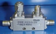
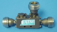
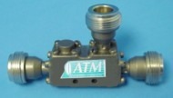
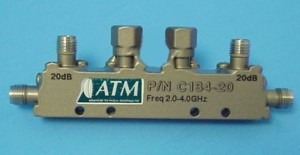
Narda-MITEQ manufactures a wide variety of broadband coaxial directional couplers. We offer coaxial single and dual directional couplers (also know as bi-directional couplers).
Narda-MITEQ coaxial directional couplers are designed, manufactured and tested in accordance with applicable military and F.A.A. standards for reliability, performance and quality. In order to assure product quality and reliability of our directional couplers, appropriate inspections and tests are made, controls exercised and data gathered to insure customer satisfaction.
The following MIL standards are utilized for all in process controls and final inspection procedures for directional couplers we manufacture: MIL-I-45208, MIL-S-454, MIL-S-202, MIL-S-883 and MIL-S-750.
Our directional couplers will meet operating specifications across the temperature range of -55 degrees C to +100 degrees C. MIL-STD-202.
| Octave Band SMA Directional Couplers | |
|---|---|
 |
Electrical |
| Freq. (GHz) | Coupling (dB) |
Freq. Sens. (+/- dB) |
Direc. (dB min.) |
Insertion Loss (dB) | VSWR max | Model No. | Outline Dwg. |
||
| Excluding Coupling |
True | Main | Sec. | ||||||
| 0.43 - 1.0 | 10+/-1.25 20+/-1.25 30+/-1.25 |
1.25 1.25 1.25 |
25 | 0.20 0.15 0.15 |
0.80 0.20 0.20 |
1.10 1.10 1.10 |
1.10 1.10 1.10 |
C111L-10 C111L-20 C111L-30 |
Fig 1 Fig 1 Fig 2 |
| 0.5 - 1.0 | 6+/-1.00 10+/-1.25 20+/-1.25 30+/-1.25 |
0.60 0.75 0.75 0.75 |
25 | 0.20 0.20 0.15 0.15 |
1.80 0.80 0.20 0.20 |
1.15 1.10 1.10 1.10 |
1.15 1.10 1.10 1.10 |
C112-6 C112-10 C112-20 C112-30 |
Fig 1 Fig 1 Fig 1 Fig 2 |
| 0.8 - 2.2 | 10+/-1.25 20+/-1.25 30+/-1.25 |
1.25 1.25 1.25 |
25 | 0.20 0.15 0.15 |
0.80 0.20 0.20 |
1.10 1.10 1.10 |
1.10 1.10 1.10 |
C113L-10 C113L-20 C113L-30 |
227646 227646 227646 |
| 1.0 - 2.0 | 6+/-1.00 10+/-1.25 20+/-1.25 30+/-1.25 |
0.60 0.75 0.75 0.75 |
25 | 0.20 0.20 0.15 0.15 |
1.80 0.80 0.20 0.20 |
1.15 1.10 1.10 1.10 |
1.15 1.10 1.10 1.10 |
C113-6 C113-10 C113-20 C113-30 |
227646 227646 227646 227646 |
| 2.0 - 4.0 | 6+/-1.00 10+/-1.25 20+/-1.25 30+/-1.25 |
0.60 0.75 0.75 0.75 |
22 | 0.20 0.20 0.15 0.15 |
1.80 0.80 0.20 0.20 |
1.15 | 1.15 | C114-6 C114-10 C114-20 C114-30 |
Fig 5 Fig 5 Fig 5 Fig 6 |
| 2.6 - 5.2 | 6+/-1.00 10+/-1.25 20+/-1.25 30+/-1.25 |
0.60 0.75 0.75 0.75 |
20 | 0.20 | 1.80 0.80 0.25 0.20 |
1.25 | 1.25 | C114F-6 C114F-10 C114F-20 C114F-30 |
Fig 7 Fig 7 Fig 7 Fig 8 |
| 4.0 - 8.0 | 6+/-1.00 10+/-1.25 20+/-1.25 30+/-1.25 |
0.60 0.75 0.75 0.75 |
20 | 0.25 | 1.90 0.90 0.30 0.25 |
1.25 | 1.25 | C115-6 C115-10 C115-20 C115-30 |
Fig 7 Fig 7 Fig 7 Fig 8 |
| 7.0 - 12.4 | 6+/-1.00 10+/-1.00 20+/-1.00 30+/-1.00 |
0.50 | 17 | 0.30 | 2.00 1.00 0.35 0.30 |
1.30 | 1.30 | C116-6 C116-10 C116-20 C116-30 |
Fig 7 Fig 7 Fig 7 Fig 8 |
| 7.5 - 16.0 | 6+/-1.00 10+/-1.25 20+/-1.25 30+/-1.25 |
0.60 0.75 0.75 0.75 |
12 12 15 15 |
0.60 | 2.20 1.20 0.65 0.60 |
1.35 | 1.40 | C116H-6 C116H-10 C116H-20 C116H-30 |
Fig 7 Fig 7 Fig 9 Fig 9 |
| 12.4 - 18.0 | 6+/-1.00 10+/-1.00 20+/-1.00 30+/-1.00 |
0.50 | 15 | 0.60 0.60 0.50 0.50 |
2.20 1.20 0.55 0.50 |
1.35 | 1.40 | C117-6 C117-10 C117-20 C117-30 |
Fig 7 Fig 7 Fig 9 Fig 9 |
| 14.0 - 21.0 | 10+/-1.50 20+/-1.50 30+/-1.50 |
0.50 | 12 | 0.80 0.70 0.70 |
1.50 0.80 0.80 |
1.65 | 1.65 | C118-10 C118-20 C118-30 |
Fig 7 Fig 9 Fig 9 |
| Octave Band, Type-N Directional Couplers | |
|---|---|
 |
Electrical |
| Freq. (GHz) | Coupling (dB) |
Freq. Sens. (+/- dB) |
Direc. (dB min.) |
Insertion Loss (dB) | VSWR max | Model No | Outline Dwg. |
||
| Excluding Coupling |
True | Main | Sec. | ||||||
| 0.5 - 1.0 | 6+/-1.00 10+/-1.25 20+/-1.25 30+/-1.25 |
0.60 0.75 0.75 0.75 |
25 | 0.20 0.20 0.15 0.15 |
1.80 0.80 0.20 0.20 |
1.20 1.15 1.15 1.15 |
1.20 1.15 1.15 1.15 |
C212-6 C212-10 C212-20 C212-30 |
Fig 1 Fig 1 Fig 1 Fig 2 |
| 1.0 - 2.0 | 6+/-1.00 10+/-1.25 20+/-1.25 30+/-1.25 |
0.60 0.75 0.75 0.75 |
25 | 0.20 0.20 0.15 0.15 |
1.80 0.80 0.20 0.20 |
1.20 1.15 1.15 1.15 |
1.20 1.15 1.15 1.15 |
C213-6 C213-10 C213-20 C213-30 |
Fig 3 Fig 3 Fig 3 Fig 3 |
| 2.0 - 4.0 | 6+/-1.00 10+/-1.25 20+/-1.25 30+/-1.25 |
0.60 0.75 0.75 0.75 |
22 | 0.20 0.20 0.15 0.15 |
1.80 0.80 0.20 0.20 |
1.20 | 1.20 | C214-6 C214-10 C214-20 C214-30 |
DWG DWG DWG DWG |
| 2.6 - 5.2 | 6+/-1.00 10+/-1.25 20+/-1.25 30+/-1.25 |
0.60 0.75 0.75 0.75 |
20 | 0.20 | 1.80 0.80 0.25 0.20 |
1.30 | 1.30 | C214F-6 C214F-10 C214F-20 C214F-30 |
Fig 8 Fig 5 Fig 5 Fig 5 |
| 4.0 - 8.0 | 6+/-1.00 10+/-1.25 20+/-1.25 30+/-1.25 |
0.60 0.75 0.75 0.75 |
20 | 0.25 | 1.90 0.90 0.30 0.25 |
1.30 | 1.30 | C215-6 C215-10 C215-20 C215-30 |
Fig 8 Fig 5 Fig 5 Fig 5 |
| 7.0 - 12.4 | 6+/-1.00 10+/-1.00 20+/-1.00 30+/-1.00 |
0.50 | 17 | 0.30 | 2.00 1.00 0.35 0.30 |
1.35 | 1.35 | C216-6 C216-10 C216-20 C216-30 |
Fig 8 Fig 8 Fig 8 Fig 9 |
| 7.5 - 16.0 | 6+/-1.00 10+/-1.25 20+/-1.25 30+/-1.25 |
0.60 0.75 0.75 0.75 |
15 | 0.60 | 2.20 1.20 0.55 0.50 |
1.40 | 1.45 | C216H-6 C216H-10 C216H-20 C216H-30 |
Fig 8 Fig 8 Fig 10 Fig 10 |
| 12.4 - 18.0 | 6+/-1.00 10+/-1.00 20+/-1.00 30+/-1.00 |
0.50 | 12 12 15 15 |
0.60 0.60 0.50 0.50 |
2.20 1.20 0.55 0.50 |
1.40 | 1.45 | C217-6 C217-10 C217-20 C217-30 |
Fig 8 Fig 8 Fig 10 Fig 10 |
| Multi-Band / Wide Band, SMA Directional Couplers | |
|---|---|
 |
Electrical |
| Freq (GHz) | Coupling (dB) |
Freq. Sens (+/- dB) |
Direc. (dB min.) |
Insertion Loss (dB) | VSWR max | Model No. | Outline Dwg. |
||
| Excluding Coupling |
True | Main | Sec | ||||||
| 0.5 - 2.0 | 6+/-1.00 10+/-1.00 20+/-1.00 30+/-1.00 |
0.75 0.75 0.75 0.80 |
23 23 23 20 |
0.35 0.35 0.35 0.40 |
2.00 0.90 0.40 0.40 |
1.20 | 1.20 | C122D-6 C122D-10 C122D-20 C122D-30 |
Fig 1 Fig 1 Fig 2 Fig 3 |
| 0.6 - 4.0 | 10+/-1.00 | 0.75 | 18 | 0.40 | 0.90 | 1.25 | 1.30 | C122E-10 | Fig 11 |
| 0.8 - 2.7 | 10+/-1.00 20+/-1.00 30+/-1.00 |
0.75 0.75 0.80 |
23 23 20 |
0.35 0.35 0.40 |
0.90 0.40 0.40 |
1.20 | 1.20 | C122L-10 C122L-20 C122L-30 |
Fig 4 Fig 4 Fig 4 |
| 1.0 - 4.0 | 6+/-1.00 10+/-1.00 20+/-1.00 |
0.50 | 23 | 0.35 0.35 0.40 |
2.00 0.90 0.45 |
1.20 | 1.20 | C123E-6 C123E-10 C123E-20 |
Fig 4 Fig 4 Fig 5 |
| 2.0 - 8.0 | 6+/-1.00 10+/-1.00 20+/-1.00 |
0.35 | 18 | 0.50 0.35 0.40 |
2.20 1.00 0.45 |
1.25 | 1.25 | C124F-6 C124F-10 C124F-20 |
Fig 6 Fig 6 Fig 7 |
| 4.0 - 12.4 | 6+/-1.00 10+/-1.00 20+/-1.00 |
0.30 0.30 0.40 |
17 | 0.50 | 2.20 1.20 0.55 |
1.30 | 1.30 | C125G-6 C125G-10 C125G-20 |
Fig 8 Fig 8 Fig 9 |
| 1.0 - 18.0 | 6+/-1.00 10+/-1.00 20+/-1.00 |
0.75 0.50 0.50 |
12 * * |
1.20 0.90 0.80 |
2.45 1.50 0.90 |
1.50 1.40 1.40 |
1.55 1.50 1.50 |
C123H-6 C123H-10 C123H-20 |
Fig 12 Fig 13 |
| 4.0 - 18.0 | 6+/-1.00 10+/-1.00 20+/-1.00 |
0.50 | * | 0.90 0.80 0.60 |
2.00 1.00 0.70 |
1.35 1.35 1.40 |
1.40 | C125H-6 C125H-10 C125H-20 |
Fig 16 Fig 16 Fig 17 |
| 6.0 - 18.0 | 10+/-1.25 20+/-1.25 |
0.60 | 15 | 0.60 | 0.60 | 1.35 | 1.40 | C126H-10 C126H-20 |
Fig 10 |
| 18.0 - 40.0 | 10+/-1.25 20+/-1.25 |
0.80 | 12 | 1.40 | 2.00 1.45 |
1.90 | 1.9 | **C128K-10 **C128K-20 |
Dwg Dwg |
| * Directivity specs as follows: | Low Freq. - 12.4GHz = 15 (dB min.) From 12.4 - 18.0GHz = 12 (dB min.) |
||||||||
| Multi-Band / Wide Band, Type-N Directional Couplers | |
|---|---|
 |
Electrical |
| Freq (GHz) | Coupling (dB) |
Freq. Sens (+/- dB) |
Direc. (dB min.) |
Insertion Loss (dB) | VSWR max | Model No. | Outline Dwg. |
||
| Excluding Coupling |
True | Main | Sec | ||||||
| 0.5 - 2.0 | 6+/-1.00 10+/-1.00 20+/-1.00 30+/-1.00 |
0.75 0.75 0.75 0.80 |
23 23 23 20 |
0.35 0.35 0.35 0.40 |
2.00 0.90 0.40 0.40 |
1.25 | 1.25 | C222D-6 C222D-10 C222D-20 C222D-30 |
Fig 1 Fig 1 Fig 2 Fig 3 |
| 0.6 - 4.0 | 10+/-1.00 | 0.75 | 18 | 0.40 | 0.90 | 1.30 | 1.35 | C222E-10 | Fig 11 |
| 0.8 - 2.7 | 10+/-1.00 20+/-1.00 30+/-1.00 |
0.75 0.75 0.80 |
23 23 20 |
0.35 0.35 0.40 |
0.90 0.40 0.40 |
1.25 | 1.25 | C222L-10 C222L-20 C222L-30 |
Fig 4 Fig 4 Fig 4 |
| 1.0 - 4.0 | 6+/-1.00 10+/-1.00 20+/-1.00 |
0.50 | 23 | 0.35 0.35 0.40 |
2.00 0.90 0.45 |
1.25 | 1.25 | C223E-6 C223E-10 C223E-20 |
Fig 4 Fig 4 Fig 5 |
| 2.0 - 8.0 | 6+/-1.00 10+/-1.00 20+/-1.00 |
0.30 0.30 0.40 |
20 | 0.50 0.35 0.40 |
2.20 1.00 0.45 |
1.30 | 1.30 | C224F-6 C224F-10 C224F-20 |
Fig 6 Fig 6 Fig 7 |
| 4.0 - 12.4 | 6+/-1.00 10+/-1.00 20+/-1.00 |
0.30 0.30 0.40 |
17 | 0.50 | 2.20 1.20 0.55 |
1.35 | 1.35 | C225G-6 C225G-10 C225G-20 |
Fig 8 Fig 8 Fig 9 |
| 1.0 - 18.0 | 10+/-1.00 20+/-1.00 |
0.50 | * | 0.90 0.80 |
1.50 0.90 |
1.45 | 1.55 | C223H-10 C223H-20 |
Fig 12 Fig 13 |
| 2.0 - 18.0 | 6+/-1.00 10+/-1.00 20+/-1.00 |
0.50 | * | 0.90 0.80 0.80 |
2.00 1.30 0.90 |
1.45 1.50 1.45 |
1.55 1.60 1.50 |
C224H-6 C224H-10 C224H-20 |
Fig 14 Fig 14 Fig 15 |
| 4.0 - 18.0 | 6+/-1.00 10+/-1.00 20+/-1.00 |
0.50 | * | 0.90 0.80 0.60 |
2.00 1.00 0.70 |
1.40 1.40 1.45 |
1.45 | C225H-6 C225H-10 C225H-20 |
Fig 16 Fig 16 Fig 17 |
| 6.0 - 18.0 | 10+/-1.25 20+/-1.25 |
0.60 | 15 | 0.60 | 0.60 | 1.40 | 1.45 | C226H-10 C226H-20 |
Fig 10 |
| * Directivity specs as follows: |
Low Freq. - 12.4GHz = 15 (dB min.) |
||||||||
| Dual Directional Coaxial Couplers - SMA | |
|---|---|
 |
Electrical |
| Freq (GHz) | Coupling (dB) |
Freq Sens (+/- dB) |
Direc. (dB min.) |
Insertion* Loss (dB) |
VSWR max | Model No. | Outline Dwg. |
|
| Main | Sec. | |||||||
| 0.5 - 1.0 | 10+/-1.25 20+/-1.25 30+/-1.25 |
0.75 | 22 | 0.20 | 1.15 | 1.10 | C132-10 C132-20 C132-30 |
Fig 1 Fig 1 Fig 2 |
| 1.0 - 2.0 | 10+/-1.25 20+/-1.25 30+/-1.25 |
0.75 | 22 | 0.25 | 1.15 | 1.10 | C133-10 C133-20 C133-30 |
Fig 3 Fig 3 Fig 4 |
| 2.0 - 4.0 | 10+/-1.25 20+/-1.25 30+/-1.25 |
0.75 | 20 | 0.40 0.30 0.30 |
1.20 | 1.15 | C134-10 C134-20 C134-30 |
Fig 5 Fig 5 Fig 6 |
| 2.6 - 5.2 | 10+/-1.25 20+/-1.25 30+/-1.25 |
0.75 | 18 | 0.20 | 1.30 | 1.25 | C134F-10 C134F-20 C134F-30 |
Fig 7 Fig 7 Fig 8 |
| 4.0 - 8.0 | 10+/-1.25 20+/-1.25 30+/-1.25 |
0.75 | 18 | 0.25 | 1.35 | 1.25 | C135-10 C135-20 C135-30 |
Fig 7 Fig 7 Fig 8 |
| 7.0 - 12.4 | 10+/-1.00 20+/-1.00 30+/-1.00 |
0.50 | 16 | 0.40 0.30 0.30 |
1.35 | 1.30 | C136-10 C136-20 C136-30 |
Fig 7 Fig 7 Fig 8 |
| 8.0 - 16.0 | 10+/-1.25 20+/-1.25 30+/-1.25 |
0.75 | 15 | 0.60 0.50 0.50 |
1.40 | 1.40 | C136H-10 C136H-20 C136H-30 |
Fig 7 Fig 9 Fig 9 |
| 12.4 - 18.0 | 10+/-1.25 20+/-1.25 30+/-1.25 |
0.60 | 15 | 0.50 | 1.40 | 1.40 | C137-10 C137-20 C137-30 |
Fig 9 Fig 9 Fig 9 |
|
* Excluding Coupled Loss Power |
||||||||