RF Power Divider / Power Splitter / Combiners - SMA |
|---|
RF Power Divider / RF Power Splitter / RF Combiner - SMA 2, 4 and 8-Way
Narda-MITEQ manufactures a wide variety of SMA 2 Way, 4 Way, and 8 Way RF Power Divider / Power Splitter / Power Combiners to meet or exceed your design specifications. We offer power divider models for octave band, multi-band, wideband, and ultra-wide band up to 40 GHz.
We also manufacture a complete line of Type-N RF Power Dividers / Power Splitters / Combiners.
Please call us to discuss your requirements for power dividers or power combiners with one of our design engineers.
Coaxial Dividers / Combiners:
Type-N Power Divider / Combiners
Waveguide:
Waveguide Power Divider / Combiners
Ka-Band:
Ka-Band Coaxial Divider / Combiners
Ka-Band WG Divider / Combiners
| 2-Way SMA Models - Power Divider / Power Combiner • Octave Band • Special Band • Multi Band • 10-40GHz Multi Band • Ultra-Wide Band |
|
|---|---|
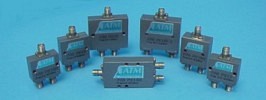 ● Stripline Construction |
Electrical |
| SMA Octave Band - Power Divider / Power Combiner 2-Way Models |
||||||||
|---|---|---|---|---|---|---|---|---|
| Freq GHz | Iso. dB |
VSWR max. | IL dB |
Amp Bal (+/- dB) |
Phase Bal (+/- Deg) |
Model No. | Outline Drawing |
|
| In | Out | |||||||
| 0.5 - 1.0 | 22 | 1.25 | 1.15 | 0.40 | 0.2 | 2.0 | P212 | Fig 1 |
| 1.0 - 2.0 | 20 | 1.25 | 1.15 | 0.35 | 0.2 | 2.0 | P213 | Fig 2 |
| 2.0 - 4.0 | 20 | 1.30 | 1.20 | 0.40 | 0.2 | 2.0 | P214 | Fig 3 |
| 4.0 - 8.0 | 20 | 1.35 | 1.25 | 0.50 | 0.2 | 2.0 | P215 | Fig 3 |
| 8.0 - 12.4 | 20 | 1.35 | 1.30 | 0.50 | 0.2 | 2.0 | P216 | Fig 4 |
| 12.0 - 18.0 | 19 | 1.40 | 1.35 | 0.60 | 0.3 | 6.0 | P217 | Fig 4 |
| 14.0 - 21.0 | 15 | 1.70 | 1.70 | 0.60 | 0.2 | 8.0 | P218 | Dwg |
| SMA Special Band - Power Divider / Power Combiner 2-Way Models |
||||||||
|---|---|---|---|---|---|---|---|---|
| Freq (GHz) | Iso. (dB) |
VSWR max. | IL (dB) |
Amp Bal (+/- dB) |
Phase Bal (+/- Deg) |
Model No. | Outline Drawing |
|
| In | Out | |||||||
| 0.85 - 1.65 | 18 | 1.25 | 1.20 | 0.40 | 0.2 | 2.0 | P213L | Fig 2 |
| 3.4 - 4.2 | 20 | 1.35 | 1.25 | 0.50 | 0.2 | 2.0 | P215C3 | Fig 3 |
| 3.65 - 6.5 | 20 | 1.35 | 1.25 | 0.40 | 0.2 | 2.0 | P215C | Fig 3 |
| 3.65 - 4.3 | 22 | 1.25 | 1.20 | 0.40 | 0.2 | 2.0 | P215C1 | Fig 3 |
| 5.85 - 6.5 | 22 | 1.25 | 1.20 | 0.40 | 0.2 | 2.0 | P215C2 | Fig 3 |
| 5.8 - 6.8 | 22 | 1.25 | 1.20 | 0.40 | 0.2 | 2.0 | P215C4 | Fig 3 |
| 7.2 - 8.4 | 20 | 1.35 | 1.30 | 0.50 | 0.2 | 2.0 | P215X | Fig 3 |
| 7.2 - 8.4 | 20 | 1.35 | 1.30 | 0.50 | 0.2 | 2.0 | P215X-1 | Fig 6 |
| 7.2 - 7.75 | 20 | 1.30 | 1.30 | 0.50 | 0.2 | 2.0 | P215X1 | Fig 3 |
| 7.2 - 7.75 | 20 | 1.30 | 1.30 | 0.50 | 0.2 | 2.0 | P215X1-1 | Fig 6 |
| 7.9 - 8.4 | 20 | 1.30 | 1.30 | 0.50 | 0.2 | 2.0 | P215X2 | Fig 3 |
| 7.9 - 8.4 | 20 | 1.30 | 1.30 | 0.50 | 0.2 | 2.0 | P215X2-1 | Fig 6 |
| 10.7 - 12.7 | 18 | 1.45 | 1.40 | 0.60 | 0.2 | 2.0 | P216X | Fig 4 |
| 10.7 - 12.7 | 20 | 1.40 | 1.35 | 0.60 | 0.2 | 2.0 | P216X-1 | Fig 7 |
| 10.7 - 14.5 | 19 | 1.40 | 1.35 | 0.70 | 0.2 | 2.0 | P216K | Fig 4 |
| 10.7 - 14.5 | 19 | 1.40 | 1.35 | 0.70 | 0.2 | 2.0 | P216K-1 | Fig 7 |
| 12.7 - 14.5 | 19 | 1.40 | 1.35 | 0.70 | 0.3 | 6.0 | P217K | Fig 4 |
| 13.7 - 14.5 | 20 | 1.40 | 1.35 | 0.60 | 0.3 | 6.0 | P217K-1 | Fig 7 |
| SMA Multi Band - Power Divider / Power Combiner 2-Way Models |
||||||||
|---|---|---|---|---|---|---|---|---|
| Freq (GHz) | Iso. (dB) |
VSWR max. | IL (dB) |
Amp Bal (+/- dB) |
Phase Bal (+/- Deg) |
Model No. | Outline Drawing |
|
| In | Out | |||||||
| 0.005 - 1.0 | 20 | 1.30 | 1.30 | 1.00 | 0.2 | 2.0 | P210CT-5-1000 | Dwg |
| 0.5 - 4.0 | 20 | 1.30 | 1.20 | 0.50 | 0.2 | 4.0 | P212E | P212E |
| 1.0 - 2.2 | 20 | 1.35 | 1.25 | 0.35 | 0.2 | 2.0 | P212D | Fig 2 |
| 1.0 - 18.0 | 18 | 1.40 | 1.40 | 1.00 | 0.2 | 5.0 | P213H** | 227304-B |
| 2.0 - 8.0 | 20 | 1.35 | 1.35 | 0.40 | 0.2 | 4.0 | P214F | Fig 5 |
| 2.0 - 18.0 | 18 | 1.40 | 1.40 | 1.00 | 0.2 | 5.0 | P214H | 227304-B |
| 5.0 - 18.0 | 19 | 1.40 | 1.35 | 0.50 | 0.3 | 6.0 | P215CK*** | Fig 4 |
| 6.0 - 18.0 | 19 | 1.40 | 1.35 | 0.60 | 0.2 | 5.0 | P215H | Fig 4 |
| 8.0 - 18.0 | 20 | 1.35 | 1.40 | 0.60 | 0.2 | 5.0 | P216H | Fig 4 |
| 2.0 - 26.5 | 19 | 1.40 | 1.35 | 1.10 | 0.3 | 6.0 | P2K8* | Fig 11 |
| *Specs for this model run from 2.0-18.0 GHz. From 18.0-26.5 GHz unit runs: ISO 12dB, VSWR 1.7 in/1.6 out, and IL 1.8 dB max. See also P214JT for another model in this band. **Specs from 1.0-2.0GHz: VSWR 1.67 in/1.40 out and Isolation 10dB. 2-18GHz as shown above. ***Specs from 5.0-6.0GHz: VSWR 1.45 in/1.40 out. |
||||||||
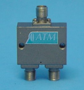
| Special 10.0 - 40.0 GHz Multi-Band Unit 2-Way Models |
 |
|||||||
|---|---|---|---|---|---|---|---|---|
| Model No. | Freq (GHz) | Iso. (dB) |
VSWR max | IL (dB) |
Amp Bal (+/- dB) |
Phase Bal (+/- Deg) |
Outline Drawing |
|
| In | Out | |||||||
| P2K9A | 10.0 - 18.0 | 18 | 1.6 | 1.5 | 1.5 | 0.6 | 6.0 | Dwg |
| 18.0 - 40.0 | 18 | 1.6 | 1.5 | 2.1 | 0.6 | 6.0 | ||
| SMA Ultra Wide Band 2-Way Models |
 |
||||||||
|---|---|---|---|---|---|---|---|---|---|
| Model No. | Freq (GHz) | Iso. (dB) |
VSWR max | IL (dB) |
Phase Balance (deg max.) |
Amplitude Balance (dB max) |
Input Power (W max) |
Outline Drawing |
|
| In | Out | ||||||||
| P213HT | 0.5 - 1.0 | 6 | 2.00 | 2.00 | 0.70 | 1.0 | 0.20 | 10 | Fig 1 |
| 1.0 - 1.5 | 10 | 1.70 | 1.50 | 0.50 | 1.0 | 0.20 | 10 | ||
| 1.5 - 2.0 | 15 | 1.60 | 1.40 | 0.50 | 1.0 | 0.20 | 10 | ||
| 2.0 - 4.0 | 20 | 1.50 | 1.30 | 0.40 | 1.0 | 0.20 | 10 | ||
| 4.0 - 8.0 | 17 | 1.50 | 1.40 | 0.50 | 1.5 | 0.20 | 10 | ||
| 8.0 - 15.0 | 15 | 1.70 | 1.50 | 0.80 | 2.0 | 0.30 | 10 | ||
| 15.0 - 16.0 | 15 | 1.70 | 1.60 | 0.80 | 3.0 | 0.30 | 10 | ||
| 16.0 - 18.0 | 14 | 1.80 | 1.90 | 0.90 | 4.0 | 0.40 | 10 | ||
| 18.0 - 20.0 | 7 | 2.00 | 2.00 | 1.10 | 4.0 | 0.40 | 10 | ||
| P214JT | 2.0 - 2.5 | 15 | 1.50 | 1.20 | 0.30 | 2.0 | 0.30 | 10 | Fig 2 |
| 2.5 - 20.0 | 20 | 1.30 | 1.30 | 1.00 | 4.0 | 0.40 | 10 | ||
| 20.0 - 26.5 | 15 | 1.50 | 1.50 | 1.50 | 6.0 | 0.40 | 10 | ||
| 4-Way SMA Models - Power Divider / Power Combiner • Octave Band • Special Band • Multi Band |
|
|---|---|
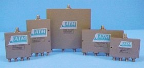 ● Stripline Construction |
Electrical |
| SMA Octave Band - Power Divider / Power Combiner 4-Way Models |
||||||||
|---|---|---|---|---|---|---|---|---|
| Freq GHz | Iso. dB |
VSWR max. | IL dB |
Amp Bal (+/- dB) |
Phase Bal (+/- Deg) |
Model No. | Outline Drawing |
|
| In | Out | |||||||
| 0.5 - 1.0 | 15 | 1.50 | 1.40 | 1.00 | 0.4 | 6.0 | P412A | Fig 9 |
| 1.0 - 2.0 | 20 | 1.40 | 1.25 | 0.80 | 0.3 | 5.0 | P413 | Fig 2 |
| 2.0 - 4.0 | 20 | 1.35 | 1.35 | 0.60 | 0.6 | 6.0 | P414 | Fig 2 |
| 4.0 - 8.0 | 17 | 1.45 | 1.35 | 0.60 | 0.3 | 4.0 | P415 | Fig 3 |
| 7.0 - 12.4 | 18 | 1.45 | 1.35 | 0.80 | 0.6 | 6.0 | P416 | Fig 4 |
| 12.0 - 18.0 | 18 | 1.50 | 1.40 | 0.90 | 0.6 | 6.0 | P417 | Fig 3 |
| 14.0 - 21.0 | 16 | 1.60 | 1.60 | 1.50 | 0.6 | 6.0 | P418 | Fig 3 |
| SMA Special Band - Power Divider / Power Combiner 4-Way Models |
||||||||
|---|---|---|---|---|---|---|---|---|
| Freq GHz | Iso. dB |
VSWR max. | IL dB |
Amp Bal (+/- dB) |
Phase Bal (+/- Deg) |
Model No. | Outline Drawing |
|
| In | Out | |||||||
| 0.85 - 1.65 | 22 | 1.25 | 1.20 | 0.40 | 0.3 | 5.0 | P413L | Fig 2 |
| 3.4 - 4.2 | 19 | 1.30 | 1.25 | 0.50 | 0.3 | 4.0 | P415C3 | Fig 2 |
| 3.65 - 6.5 | 20 | 1.35 | 1.25 | 0.40 | 0.3 | 4.0 | P415C | Fig 3 |
| 3.65 - 4.3 | 22 | 1.25 | 1.20 | 0.40 | 0.3 | 4.0 | P415C1 | Fig 2 |
| 5.85 - 6.5 | 22 | 1.25 | 1.20 | 0.40 | 0.3 | 4.0 | P415C2 | Fig 3 |
| 7.2 - 8.4 | 20 | 1.35 | 1.30 | 0.50 | 0.3 | 4.0 | P415X | Fig 3 |
| 7.2 - 7.75 | 20 | 1.30 | 1.30 | 0.50 | 0.3 | 4.0 | P415X1 | Fig 3 |
| 7.9 - 8.4 | 20 | 1.30 | 1.30 | 0.50 | 0.3 | 4.0 | P415X2 | Fig 3 |
| 10.7 - 12.7 | 18 | 1.40 | 1.35 | 0.60 | 0.6 | 6.0 | P416X-1 | Fig 5 |
| 10.7 - 14.5 | 18 | 1.45 | 1.40 | 0.60 | 0.6 | 6.0 | P416K-1 | Fig 5 |
| 13.7 - 14.5 | 18 | 1.40 | 1.35 | 0.60 | 0.6 | 6.0 | P417K-1 | Fig 5 |
| 5.7 - 18.5 | 12 | 1.70 | 1.60 | 2.00 | 0.3 | 4.0 | P415CJ | Dwg |
| SMA Multi Band - Power Divider / Power Combiner 4-Way Models |
||||||||
|---|---|---|---|---|---|---|---|---|
| Freq GHz | Iso. dB |
VSWR max. | IL dB |
Amp Bal (+/- dB) |
Phase Shift (+/- Deg) |
Model No. | Outline Drawing |
|
| In | Out | |||||||
| 0.8 - 2.2 | 15 | 1.50 | 1.40 | 1.00 | 0.4 | 6.0 | P412D | Fig 9 |
| 0.5 - 2.5 | 15 | 1.50 | 1.40 | 1.00 | 0.4 | 6.0 | P412D-.5-2.5 | Fig 9 |
| 0.5 - 4.0 | 15 | 1.50 | 1.40 | 1.00 | 0.4 | 7.0 | P412E | Fig 6 |
| 2.0 - 8.0 | 15 | 1.70 | 1.40 | 2.00 | 0.4 | 7.0 | P414F | Fig 7 |
| 2.0 - 18.0 | 14 | 1.70 | 1.50 | 1.50 | 0.6 | 10.0 | P414H | Dwg |
| 2.0 - 18.0 | 16 | 1.70 | 1.40 | 2.30 | 0.8 | 10.0 | P414HA | Dwg |
| 6.0 - 18.0 | 18 | 1.60 | 1.40 | 1.30 | 0.6 | 6.0 | P415H | Fig 3 |
| 8.0 - 18.0 | 18 | 1.40 | 1.50 | 1.30 | 0.6 | 6.0 | P416H | Fig 3 |
| 8-Way SMA Models - Power Divider / Power Combiner • Octave Band • Special Band • Multi Band |
|
|---|---|
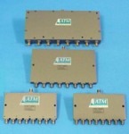 ● Stripline Construction ● Compact & Lightweight ● Most popular models in stock for fast delivery ● Octave Band, Special Band, Multi Band and Ultra Wide Band models available |
Electrical |
| SMA Octave Band - Power Divider / Power Combiner 8-Way Models |
||||||||
|---|---|---|---|---|---|---|---|---|
| Freq GHz | Iso. dB |
VSWR max. | IL dB |
Amp Bal (+/- dB) |
Phase Bal (+/- Deg) |
Model No. | Outline Drawing |
|
| In | Out | |||||||
| 0.5 - 1.0 | 18 | 1.45 | 1.30 | 0.90 | 0.4 | 5.0 | P812 | Fig 1 |
| 1.0 - 2.0 | 18 | 1.45 | 1.35 | 0.80 | 0.3 | 5.0 | P813 | Fig 2 |
| 2.0 - 4.0 | 18 | 1.45 | 1.35 | 0.80 | 0.4 | 5.0 | P814 | Fig 3 |
| 4.0 - 8.0 | 17 | 1.45 | 1.40 | 1.00 | 0.8 | 6.0 | P815 | Fig 3 |
| 8.0 - 12.4 | 16 | 1.70 | 1.70 | 1.40 | 0.5 | 12.0 | P816 | Fig 7 |
| 12.0 - 18.0 | 15 | 1.80 | 1.50 | 2.00 | 0.4 | 6.0 | P817 | Fig 3 |
| SMA Special Band - Power Divider / Power Combiner 8-Way Models |
||||||||
|---|---|---|---|---|---|---|---|---|
| Freq GHz | Iso. dB |
VSWR max. | IL dB |
Amp Bal (+/- dB) |
Phase Bal (+/- Deg) |
Model No. | Outline Drawing |
|
| In | Out | |||||||
| 0.85 - 1.65 | 18 | 1.45 | 1.40 | 0.80 | 0.3 | 5.0 | P813L | Fig 2 |
| 3.4 - 4.2 | 18 | 1.40 | 1.30 | 0.70 | 0.8 | 6.0 | P815C3 | Fig 3 |
| 3.65 - 6.5 | 17 | 1.45 | 1.45 | 0.80 | 0.8 | 6.0 | P815C | Fig 3 |
| 3.65 - 4.3 | 18 | 1.40 | 1.40 | 0.80 | 0.8 | 6.0 | P815C1 | Fig 3 |
| 5.85 - 6.5 | 18 | 1.45 | 1.40 | 0.80 | 0.8 | 6.0 | P815C2 | Fig 3 |
| 7.2 - 8.4 | 16 | 1.45 | 1.40 | 0.90 | 0.8 | 6.0 | P815X | Fig 7 |
| 7.2 - 7.75 | 16 | 1.45 | 1.40 | 0.90 | 0.8 | 6.0 | P815X1 | Fig 7 |
| 7.9 - 8.4 | 16 | 1.45 | 1.40 | 0.90 | 0.8 | 6.0 | P815X2 | Fig 7 |
| 10.7 - 12.7 | 17 | 1.45 | 1.40 | 1.00 | 0.5 | 6.0 | P816X-1 | Fig 4 |
| 10.7 - 14.5 | 17 | 1.45 | 1.40 | 1.00 | 0.5 | 6.0 | P816K-1 | Fig 4 |
| 13.7 - 14.5 | 17 | 1.45 | 1.40 | 1.00 | 0.4 | 6.0 | P817K-1 | Fig 4 |
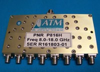
| SMA Multi Band 8-Way Models |
 |
|||||||
|---|---|---|---|---|---|---|---|---|
| Freq GHz | Iso. dB |
VSWR max. | IL dB |
Amp Bal (+/- dB) |
Phase Bal (+/- Deg) |
Model No. | Outline Drawing | |
| In | Out | |||||||
| 2.0 - 18.0 | 13 | 1.80 | 1.70 | 3.40 | 1.1 | 18.0 | P814HA | Dwg |
| 8.0 - 18.0 | 15 | 1.80 | 1.50 | 2.00 | 0.6 | 6.0 | P816H | Fig 6 |