| 06 Series Continuously Variable Attenuators | |||
|---|---|---|---|
|
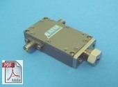
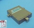
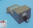
Standard Model |
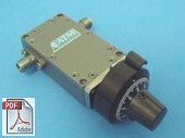
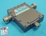
Turns Counting Dial Option |
||
|
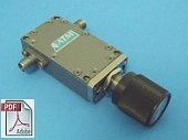
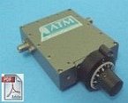
Knob Control Option |
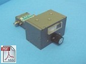
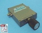
Direct Reading in dB Option |
||
|
|||
|
GENERAL SPECIFICATIONS - 06 SERIES CVA |
|
|---|---|
|
Applicable Mil-Specs |
Mechanical |
| 06 Series CVA Frequency Flat Models, Narrow Band |
||||
|---|---|---|---|---|
| Freq (GHz) | Atten Range dB |
VSWR Max |
Flatness +/- dB |
Model No. |
| 3.4 - 4.2 | 10 | 1.5 | 0.5 | AF065C3-10 |
| 3.4 - 4.2 | 20 | 1.5 | 1.0 | AF065C3-20 |
| 3.6 - 6.5 | 10 | 1.5 | 0.8 | AF065C-10 |
| 3.6 - 6.5 | 20 | 1.5 | 1.5 | AF065C-20 |
| 3.6 - 4.3 | 10 | 1.5 | 0.3 | AF065C1-10 |
| 3.6 - 4.3 | 20 | 1.5 | 0.5 | AF065C1-20 |
| 5.8 - 6.5 | 10 | 1.5 | 0.3 | AF065C2-10 |
| 5.8 - 6.5 | 20 | 1.5 | 0.5 | AF065C2-20 |
| 5.8 - 6.5 | 30 | 1.5 | 1.0 | AF065C2-30 |
| 7.2 - 8.4 | 10 | 1.5 | 0.5 | AF065X-10 |
| 7.2 - 8.4 | 20 | 1.5 | 1.0 | AF065X-20 |
| 7.2 - 8.4 | 30 | 1.5 | 1.5 | AF065K-30 |
| 7.2 - 7.8 | 10 | 1.5 | 0.25 | AF065X1-10 |
| 7.2 - 7.8 | 20 | 1.5 | 0.5 | AF065X1-20 |
| 7.2 - 7.8 | 30 | 1.5 | 0.75 | AF065X1-30 |
| 7.9 - 8.4 | 10 | 1.5 | 0.25 | AF065X2-10 |
| 7.9 - 8.4 | 20 | 1.5 | 0.5 | AF065X2-20 |
| 7.9 - 8.4 | 30 | 1.5 | 0.75 | AF065X2-30 |
| 10.7 - 12.7 | 10 | 1.5 | 0.5 | AF066X-10 |
| 10.7 - 12.7 | 20 | 1.5 | 0.8 | AF066X-20 |
| 10.7 - 12.7 | 30 | 1.5 | 1.2 | AF066X-30 |
| 10.7 - 14.5 | 10 | 1.5 | 1.0 | AF066K-10 |
| 10.7 - 14.5 | 20 | 1.5 | 1.5 | AF066K-20 |
| 10.7 - 14.5 | 30 | 1.5 | 1.75 | AF066K-30 |
| 12.4 - 18.0 | 10 | 1.5 | 1.0 | AF067-10 |
| 13.0 - 14.5 | 10 | 1.5 | 0.2 | AF067K-10 |
| 13.0 - 14.5 | 20 | 1.5 | 0.3 | AF067K-20 |
| 13.0 - 14.5 | 30 | 1.5 | 0.5 | AF067K-30 |
| 17.0 - 18.6 | 10 | 1.5 | 0.75 | AF067J-10 |
| 17.0 - 18.6 | 20 | 1.5 | 1.0 | AF067J-20 |
| 17.0 - 18.6 | 30 | 1.5 | 1.5 | AF067J-30 |
| 17.0 - 18.6 | 40 | 1.5 | 2.0 | AF067J-40 |
| * Tri-band units, flatness spec is per band: C (5.85-6.45GHz), X (7.9-8.4GHz), Ku (14-14.5GHz) |
||||
| 06 Series CVA Frequency Flat Models, Octave Band |
||||
|---|---|---|---|---|
| Freq (GHz) | Atten Range dB |
VSWR Max |
Flatness +/- dB |
Model No. |
| 2.0 - 4.0 | 10 | 1.6 | 2.0 | AF064-10 |
| 4.0 - 8.0 | 10 | 1.5 | 2.0 | AF065-10 |
| 8.0 - 12.4 | 10 | 1.5 | 1.0 | AF066-10 |
| 12.4 - 18.0 | 10 | 1.5 | 1.0 | AF067-10 |
| 14.0 - 26.5 | 10 | 1.7 | 0.8 | AF068-10 |
| 14.0 - 26.5 | 20 | 1.7 | 1.0 | AF068-20 |
| 14.0 - 26.5 | 30 | 1.7 | 1.5 | AF068-30 |
| 26.5 - 40.0 | 10 | 2.0 | 1.25 | AF069-10 |
| 26.5 - 40.0 | 20 | 2.0 | 1.50 | AF069-20 |
| 26.5 - 40.0 | 30 | 2.0 | 1.80 | AF069-30 |
| 06 Series CVA Frequency Flat Models, Wide Band |
||||
|---|---|---|---|---|
| Freq (GHz) | Atten Range dB |
VSWR Max |
Flatness +/- dB |
Model No. |
| 4.0 - 12.4 | 10 | 1.7 | 1.0 | AF065G-10 |
| 5.85 - 14.5 | 10 | 1.5 | 0.5/B* | AF06CK-10 |
| 5.85 - 14.5 | 20 | 1.5 | 0.5/B* | AF06CK-20 |
| 5.85 - 14.5 | 30 | 1.5 | 1.0/B* | AF06CK-30 |
| 8.0 - 18.0 | 10 | 1.7 | 1.5 | AF066H-10 |
| 8.0 - 18.0 | 20 | 1.7 | 1.8 | AF066H-20 |
| *Tri-band units, flatness spec is per band: C (5.85-6.45 GHz), X (7.9-8.4 Ghz), Ku (14-14.5 GHz) |
||||
| 06 Series CVA Level Adjust Models, Octave Band Models |
||||
|---|---|---|---|---|
| Freq (GHz) | Atten Range dB |
VSWR Max |
Flatness +- dB |
Model No. |
| 2.0 - 4.2 | 10 | 1.5 | N/A | AV064-10 |
| 3.7 - 8.0 | 10 | 1.5 | N/A | AV065-10 |
| 3.7 - 8.0 | 20 | 1.5 | N/A | AV065-20 |
| 7.9 - 12.7 | 10 | 1.5 | N/A | AV066-10 |
| 7.9 - 12.7 | 20 | 1.5 | N/A | AV066-20 |
| 7.9 - 12.7 | 30 | 1.5 | N/A | AV066-30 |
| 11.7 - 18.0 | 10 | 1.5 | N/A | AV067-10 |
| 11.7 - 18.0 | 20 | 1.5 | N/A | AV067-20 |
| 11.7 - 18.0 | 30 | 1.5 | N/A | AV067-30 |
| 11.7 - 18.0 | 40 | 1.5 | N/A | AV067-40 |
| 14.0 - 26.5 | 10 | 1.7 | N/A | AV068-10 |
| 14.0 - 26.5 | 20 | 1.7 | N/A | AV068-20 |
| 14.0 - 26.5 | 30 | 1.7 | N/A | AV068-30 |
| 14.0 - 26.5 | 40 | 1.7 | N/A | AV068-40 |
| 26.5 - 40.0 | 10 | 2.0 | N/A | AV069-10 |
| 26.5 - 40.0 | 20 | 2.0 | N/A | AV069-20 |
| 26.5 - 40.0 | 30 | 2.0 | N/A | AV069-30 |
| 26.5 - 40.0 | 40 | 2.0 | N/A | AV069-40 |
| 06 Series CVA Level Adjust Models, Wide Band Models |
||||
|---|---|---|---|---|
| Freq (GHz) | Atten Range dB |
VSWR Max |
Flatness +- dB |
Model No. |
| 2.0 - 8.0 | 10 | 1.5 | N/A | AV064F-10 |
| 4.0 - 12.4 | 10 | 1.5 | N/A | AV065G-10 |
| 4.0 - 18.0 | 10 | 1.5 | N/A | AV065H-10 |
| 6.0 - 18.0 | 10 | 1.5 | N/A | AV066H-10 |
| 6.0 - 18.0 | 20 | 1.5 | N/A | AV066H-20 |
| 6.0 - 18.0 | 30 | 1.5 | N/A | AV066H-30 |
| 10.0 - 26.5 | 10 | 1.8 | N/A | AV066J-10 |
| 10.0 - 26.5 | 20 | 1.8 | N/A | AV066J-20 |
| 18.0 - 40.0 | 10 | 2.0 | N/A | AV068Q-10 |
| 18.0 - 40.0 | 20 | 2.0 | N/A | AV068Q-20 |
| 07 Series Continuously Variable Attenuators | |||
|---|---|---|---|
|
Standard Model |
Turns Counting Dial Option |
||
|
Knob Control Option |
Direct Reading in dB Option |
||
|
|||
|
GENERAL SPECIFICATIONS - 07 SERIES CVA |
|
|---|---|
|
Applicable Mil-Specs |
Mechanical |
| 07 Series Variable Attenuators Frequency Flat Models |
||||
|---|---|---|---|---|
| Freq (GHz) | Atten. Range dB |
VSWR Max |
Flatness +/- dB |
Model No. |
| 2.0 - 4.0 | 10 | 1.7 | 1.5 | AF074-10 |
| 3.4 - 4.2 | 10 | 1.5 | 0.5 | AF075C3-10 |
| 3.4 - 4.2 | 20 | 1.5 | 1.0 | AF075C3-20 |
| 3.6 - 6.5 | 10 | 1.5 | 0.8 | AF075C-10 |
| 3.6 - 6.5 | 20 | 1.5 | 1.25 | AF075C-20 |
| 3.6 - 6.5 | 30 | 1.5 | 1.75 | AF075C-30 |
| 3.6 - 4.3 | 10 | 1.5 | 0.3 | AF075C1-10 |
| 3.6 - 4.3 | 20 | 1.5 | 0.5 | AF075C1-20 |
| 3.6 - 4.3 | 30 | 1.5 | 0.75 | AF075C1-30 |
| 5.8 - 6.5 | 10 | 1.5 | 0.3 | AF075C2-10 |
| 5.8 - 6.5 | 20 | 1.5 | 0.5 | AF075C2-20 |
| 5.8 - 6.5 | 30 | 1.5 | 0.75 | AF075C2-30 |
| 5.85 - 14.5 | 10 | 1.5 | 0.5/B* | AF07CK-10 |
| 5.85 - 14.5 | 20 | 1.5 | 0.5/B* | AF07CK-20 |
| 5.85 - 14.5 | 30 | 1.5 | 0.5/B* | AF07CK-30 |
| 4.0 - 8.0 | 10 | 1.5 | 2.0 | AF075-10 |
| 4.0 - 12.4 | 10 | 1.9 | 1.75 | AF075G-10 |
| 7.2 - 8.4 | 10 | 1.5 | 0.5 | AF075X-10 |
| 7.2 - 8.4 | 20 | 1.5 | 1.0 | AF075X-20 |
| 7.2 - 8.4 | 30 | 1.5 | 1.5 | AF075X-30 |
| 7.2 - 8.4 | 40 | 1.5 | 2.0 | AF075X-40 |
| 7.2 - 7.8 | 10 | 1.5 | 0.3 | AF075X1-10 |
| 7.2 - 7.8 | 20 | 1.5 | 0.4 | AF075X1-20 |
| 7.2 - 7.8 | 30 | 1.5 | 0.5 | AF075X1-30 |
| 7.2 - 7.8 | 40 | 1.5 | 1.0 | AF075X1-40 |
| 7.9 - 8.5 | 10 | 1.5 | 0.3 | AF075X2-10 |
| 7.9 - 8.5 | 20 | 1.5 | 0.4 | AF075X2-20 |
| 7.9 - 8.5 | 30 | 1.5 | 0.5 | AF075X2-30 |
| 7.9 - 8.5 | 40 | 1.5 | 1.0 | AF075X2-40 |
| 8.0 - 12.4 | 10 | 1.5 | 1.0 | AF076-10 |
| 8.0 - 12.4 | 20 | 1.5 | 2.0 | AF076-20 |
| 8.0 - 18.0 | 10 | 1.6 | 1.5 | AF076H-10 |
| 8.0 - 18.0 | 20 | 1.6 | 2.0 | AF076H-20 |
| 10.7 - 12.75 | 10 | 1.5 | 0.5 | AF076X-10 |
| 10.7 - 12.75 | 20 | 1.5 | 0.8 | AF076X-20 |
| 10.7 - 12.75 | 30 | 1.5 | 1.2 | AF076X-30 |
| 10.7 - 12.75 | 40 | 1.5 | 1.75 | AF076X-40 |
| 10.7 - 14.5 | 10 | 1.5 | 1.0 | AF076K-10 |
| 10.7 - 14.5 | 20 | 1.5 | 1.5 | AF076K-20 |
| 10.7 - 14.5 | 30 | 1.5 | 1.75 | AF076K-30 |
| 10.7 - 14.5 | 40 | 1.5 | 2.0 | AF076K-40 |
| 12.4 - 18.0 | 10 | 1.5 | 1.0 | AF077-10 |
| 12.4 - 18.0 | 20 | 1.5 | 1.75 | AF077-20 |
| 17.0 - 18.6 | 10 | 1.5 | 0.75 | AF077J-10 |
| 17.0 - 18.6 | 20 | 1.5 | 1.0 | AF077J-20 |
| 17.0 - 18.6 | 30 | 1.5 | 1.5 | AF077J-30 |
| 17.0 - 18.6 | 40 | 1.5 | 2.0 | AF077J-40 |
| * Tri-band units, flatness spec is per band: C (5.85-6.45GHz), X (7.9-8.4GHz), Ku (14-14.5GHz) |
||||
| 07 Series Variable Attenuators Level Adjust Models, Octave Band Models |
||||
|---|---|---|---|---|
| Freq (GHz) | Atten. Range dB |
VSWR Max |
Flatness +- dB |
Model No. |
| 1.0 - 2.0 | 10 | 1.8 | N/A | AV073-10 |
| 1.5 - 2.0 | 15 | 1.5 | N/A | AV073-15 |
| 2.0 - 4.0 | 10 | 1.5 | N/A | AV074-10 |
| 2.0 - 4.0 | 20 | 1.5 | N/A | AV074-20 |
| 2.0 - 8.0 | 10 | 1.5 | N/A | AV074F-10 |
| 2.0 - 8.0 | 20 | 1.5 | N/A | AV074F-20 |
| 3.6 - 4.3 | 10 | 1.5 | N/A | AV075C1-10 |
| 3.6 - 4.3 | 20 | 1.5 | N/A | AV075C1-20 |
| 3.6 - 4.3 | 30 | 1.5 | N/A | AV075C1-30 |
| 3.6 - 4.3 | 40 | 1.5 | N/A | AV075C1-40 |
| 4.0 - 8.0 | 10 | 1.5 | N/A | AV075-10 |
| 4.0 - 8.0 | 20 | 1.5 | N/A | AV075-20 |
| 4.0 - 8.0 | 30 | 1.5 | N/A | AV075-30 |
| 4.0 - 12.4 | 10 | 1.5 | N/A | AV075G-10 |
| 4.0 - 12.4 | 20 | 1.5 | N/A | AV075G-20 |
| 4.0 - 12.4 | 30 | 1.5 | N/A | AV075G-30 |
| 8.0 - 12.4 | 10 | 1.5 | N/A | AV076-10 |
| 8.0 - 12.4 | 20 | 1.5 | N/A | AV076-20 |
| 8.0 - 12.4 | 30 | 1.5 | N/A | AV076-30 |
| 8.0 - 12.4 | 40 | 1.5 | N/A | AV076-40 |
| 8.0 - 18.0 | 10 | 1.5 | N/A | AV076H-10 |
| 8.0 - 18.0 | 20 | 1.5 | N/A | AV076H-20 |
| 8.0 - 18.0 | 30 | 1.5 | N/A | AV076H-30 |
| 8.0 - 18.0 | 40 | 1.5 | N/A | AV076H-40 |
| 08 Series Continuously Variable Attenuators | |||
|---|---|---|---|
|
Standard Model |
Type-N Model |
||
|
Turns Counting Dial Option |
Knob Control Option |
||
|
Direct Reading in dB Option |
|||
|
|||
|
GENERAL SPECIFICATIONS - 08 SERIES CVA |
|
|---|---|
|
Applicable Mil-Specs |
Mechanical |
| 08 Series CVA Frequency Flat, Special Band Models |
||||
|---|---|---|---|---|
| Freq (GHz) | Atten. Range dB |
VSWR Max |
Flatness +/- dB |
Model No. |
| 0.7 - 0.8 | 10 | 1.8 | 0.75 | AF082L2-10 |
| 0.8 - 1.0 | 10 | 1.8 | 0.75 | AF082L1-10 |
| 0.8 - 1.0 | 15 | 1.8 | 1.0 | AF082L1-15 |
| 0.8 - 1.0 | 20 | 1.8 | 1.5 | AF082L1-20 |
| 0.95 - 1.45 | 10 | 1.8 | 1.5 | AF083L1-10 |
| 0.95 - 1.45 | 15 | 1.8 | 1.7 | AF083L1-15 |
| 1.5 - 2.0 | 10 | 1.5 | 1.25 | AF083L2-10 |
| 1.5 - 2.0 | 20 | 1.5 | 1.5 | AF083L2-20 |
| 3.4 - 4.2 | 10 | 1.5 | 0.75 | AF085C3-10 |
| 3.4 - 4.2 | 20 | 1.5 | 1.0 | AF085C3-20 |
| 3.4 - 4.2 | 30 | 1.5 | 1.5 | AF085C3-30 |
| 3.4 - 4.2 | 40 | 1.5 | 2.0 | AF085C3-40 |
| 3.6 - 4.3 | 10 | 1.5 | 0.3 | AF085C1-10 |
| 3.6 - 4.3 | 20 | 1.5 | 0.5 | AF085C1-20 |
| 3.6 - 4.3 | 30 | 1.5 | 0.75 | AF085C1-30 |
| 3.6 - 4.3 | 40 | 1.5 | 1.25 | AF085C1-40 |
| 3.6 - 6.5 | 10 | 1.5 | 0.5 | AF085C-10 |
| 3.6 - 6.5 | 20 | 1.5 | 0.8 | AF085C-20 |
| 3.6 - 6.5 | 30 | 1.5 | 1.25 | AF085C-30 |
| 3.6 - 6.5 | 40 | 1.5 | 1.75 | AF085C-40 |
| 5.8 - 6.5 | 10 | 1.5 | 0.3 | AF085C2-10 |
| 5.8 - 6.5 | 20 | 1.5 | 0.5 | AF085C2-20 |
| 5.8 - 6.5 | 30 | 1.5 | 0.75 | AF085C2-30 |
| 5.8 - 6.5 | 40 | 1.5 | 1.25 | AF085C2-40 |
| 5.8 - 6.5 | 50 | 1.5 | 2 | AF085C2-50 |
| 7.2 - 7.8 | 10 | 1.5 | 0.15 | AF085X1-10 |
| 7.2 - 7.8 | 20 | 1.5 | 0.25 | AF085X1-20 |
| 7.2 - 7.8 | 30 | 1.5 | 0.40 | AF085X1-30 |
| 7.2 - 7.8 | 40 | 1.5 | 0.75 | AF085X1-40 |
| 7.2 - 7.8 | 50 | 1.5 | 1.25 | AF085X1-50 |
| 7.2 - 8.4 | 10 | 1.5 | 0.3 | AF085X-10 |
| 7.2 - 8.4 | 20 | 1.5 | 0.5 | AF085X-20 |
| 7.2 - 8.4 | 30 | 1.5 | 0.75 | AF085X-30 |
| 7.2 - 8.4 | 40 | 1.5 | 1.25 | AF085X-40 |
| 7.2 - 8.4 | 50 | 1.5 | 2.00 | AF085X-50 |
| 7.9 - 8.4 | 10 | 1.5 | 0.15 | AF085X2-10 |
| 7.9 - 8.4 | 20 | 1.5 | 0.25 | AF085X2-20 |
| 7.9 - 8.4 | 30 | 1.5 | 0.40 | AF085X2-30 |
| 7.9 - 8.4 | 40 | 1.5 | 0.75 | AF085X2-40 |
| 7.9 - 8.4 | 50 | 1.5 | 1.25 | AF085X2-50 |
| 10.7 - 12.7 | 10 | 1.5 | 0.5 | AF086X-10 |
| 10.7 - 12.7 | 20 | 1.5 | 0.8 | AF086X-20 |
| 10.7 - 12.7 | 30 | 1.5 | 1.0 | AF086X-30 |
| 10.7 - 12.7 | 40 | 1.5 | 1.5 | AF086X-40 |
| 10.7 - 12.7 | 50 | 1.5 | 1.9 | AF086X-50 |
| 10.7 - 14.5 | 10 | 1.5 | 0.75 | AF086K-10 |
| 10.7 - 14.5 | 20 | 1.5 | 1.0 | AF086K-20 |
| 10.7 - 14.5 | 30 | 1.5 | 1.5 | AF086K-30 |
| 10.7 - 14.5 | 40 | 1.5 | 1.75 | AF086K-40 |
| 10.7 - 14.5 | 50 | 1.5 | 2.25 | AF086K-50 |
| 13.0 - 14.5 | 10 | 1.5 | 0.5 | AF087K-10 |
| 13.0 - 14.5 | 20 | 1.5 | 0.6 | AF087K-20 |
| 13.0 - 14.5 | 30 | 1.5 | 0.7 | AF087K-30 |
| 13.0 - 14.5 | 40 | 1.5 | 0.8 | AF087K-40 |
| 13.0 - 14.5 | 50 | 1.5 | 1.0 | AF087K-50 |
| 08 Series CVA Frequency Flat, Octave Band Models |
||||
|---|---|---|---|---|
| Freq (GHz) | Atten. Range dB |
VSWR Max |
Flatness +/- dB |
Model No. |
| 2.0 - 4.0 | 10 | 1.5 | 1.25 | AF084-10 |
| 2.0 - 4.0 | 20 | 1.5 | 1.5 | AF084-20 |
| 2.0 - 4.0 | 30 | 1.5 | 2.5 | AF084-30 |
| 4.0 - 8.0 | 10 | 1.5 | 0.75 | AF085-10 |
| 4.0 - 8.0 | 20 | 1.5 | 1.5 | AF085-20 |
| 4.0 - 8.0 | 30 | 1.5 | 2.5 | AF085-30 |
| 8.0 - 12.4 | 10 | 1.5 | 0.75 | AF086-10 |
| 8.0 - 12.4 | 20 | 1.5 | 1.0 | AF086-20 |
| 8.0 - 12.4 | 30 | 1.5 | 1.5 | AF086-30 |
| 12.4 - 18.0 | 10 | 1.5 | 0.75 | AF087-10 |
| 12.4 - 18.0 | 20 | 1.5 | 1.5 | AF087-20 |
| 12.4 - 18.0 | 30 | 1.5 | 2.0 | AF087-30 |
| 12.4 - 18.0 | 40 | 1.5 | 2.5 | AF087-40 |
| 08 Series CVA Frequency Flat, Wide Band Models |
||||
|---|---|---|---|---|
| Freq (GHz) | Atten. Range dB |
VSWR Max |
Flatness +/- dB |
Model No. |
| 2.8 - 6.5 | 10 | 1.5 | 1.25 | AF084F-10 |
| 2.8 - 6.5 | 20 | 1.5 | 1.5 | AF084F-20 |
| 4.0 - 18.0 | 10 | 1.5 | 4.0 | AF085H-10 |
| 4.0 - 18.0 | 20 | 1.5 | 5.0 | AF085H-20 |
| 08 Series CVA Level Adjust Models, Octave Band Models |
||||
|---|---|---|---|---|
| Freq (GHz) | Atten. Range dB |
VSWR Max |
Flatness +- dB |
Model No. |
| 0.7 - 1.0 | 10 | 1.7 | N/A | AV082-10 |
| 0.8 - 1.0 | 10 | 1.7 | N/A | AV082L-10 |
| 0.8 - 1.0 | 15 | 1.7 | N/A | AV082L-15 |
| 0.8 - 1.0 | 20 | 1.7 | N/A | AV082L-20 |
| 0.8 - 1.6 | 10 | 1.7 | N/A | AV083L-10 |
| 0.8 - 1.6 | 15 | 1.7 | N/A | AV083L-15 |
| 0.8 - 2.0 | 20 | 1.7 | N/A | AV083L-20 |
| 0.9 -1.75 | 15 | 1.7 | N/A | AV083-15B |
| 0.9 - 1.8 | 10 | 1.7 | N/A | AV083L1-10 |
| 0.9 - 1.8 | 15 | 1.7 | N/A | AV083L1-15 |
| 0.95 - 2.0 | 10 | 1.7 | N/A | AV083L2-10 |
| 0.95 - 2.0 | 20 | 1.7 | N/A | AV083L2-20 |
| 0.95 - 2.0 | 25 | 1.7 | N/A | AV083L2-25 |
| 1.0 - 2.0 | 10 | 1.5 | N/A | AV083-10 |
| 1.0 - 2.0 | 15 | 1.5 | N/A | AV083-15 |
| 1.0 - 2.0 | 20 | 1.5 | N/A | AV083-20 |
| 1.5 - 3.0 | 10 | 1.5 | N/A | AV083D-10 |
| 1.5 - 3.0 | 20 | 1.5 | N/A | AV083D-20 |
| 1.5 - 3.0 | 30 | 1.5 | N/A | AV083D-30 |
| 1.7 - 2.7 | 10 | 1.5 | N/A | AV083L3-10 |
| 1.7 - 2.7 | 20 | 1.5 | N/A | AV083L3-20 |
| 1.7 - 2.7 | 30 | 1.5 | N/A | AV083L3-30 |
| 1.7 - 2.7 | 40 | 1.5 | N/A | AV083L3-40 |
| 2.0 - 4.2 | 10 | 1.5 | NA | AV084-10 |
| 2.0 - 4.2 | 20 | 1.5 | N/A | AV084-20 |
| 2.0 - 4.2 | 30 | 1.5 | N/A | AV084-30 |
| 4.0 - 8.0 | 10 | 1.5 | N/A | AV085-10 |
| 4.0 - 8.0 | 20 | 1.5 | N/A | AV085-20 |
| 4.0 - 8.0 | 30 | 1.5 | N/A | AV085-30 |
| 4.0 - 8.0 | 40 | 1.5 | N/A | AV085-40 |
| 7.9 - 12.7 | 10 | 1.5 | N/A | AV086-10 |
| 7.9 - 12.7 | 20 | 1.5 | N/A | AV086-20 |
| 7.9 - 12.7 | 30 | 1.5 | N/A | AV086-30 |
| 7.9 - 12.7 | 40 | 1.5 | N/A | AV086-40 |
| 11.7 - 18.0 | 10 | 1.5 | N/A | AV087-10 |
| 11.7 - 18.0 | 20 | 1.5 | N/A | AV087-20 |
| 11.7 - 18.0 | 30 | 1.5 | N/A | AV087-30 |
| 11.7 - 18.0 | 40 | 1.5 | N/A | AV087-40 |
| 08 Series CVA Wide Band Models |
||||
|---|---|---|---|---|
| Freq (GHz) | Atten. Range dB |
VSWR Max |
Flatness +- dB |
Model No. |
| 0.7 - 2.0 | 10 | 1.7 | N/A | AV082D-10 |
| 0.85 - 2.7 | 10 | 1.7 | N/A | AV082E-10 |
| 0.85 - 2.7 | 15 | 1.7 | N/A | AV082E-15 |
| 0.85 - 2.7 | 20 | 1.7 | N/A | AV082E-20 |
| 0.9 - 8.0 | 10 | 1.8 | N/A | AV083F-10* |
| 0.9 - 8.0 | 20 | 1.8 | N/A | AV083F-20* |
| 1.0 - 4.0 | 10 | 1.8 | N/A | AV083E-10 |
| 1.0 - 4.0 | 20 | 1.8 | N/A | AV083E-20 |
| 1.0 - 4.0 | 30** | 1.8 | N/A | AV083E-30 |
| 1.0 - 8.0 | 30** | 1.8 | N/A | AV083F-30 |
| 2.0 - 8.0 | 10 | 1.5 | N/A | AV084F-10 |
| 2.0 - 8.0 | 20 | 1.5 | N/A | AV084F-20 |
| 2.0 - 8.0 | 30 | 1.5 | N/A | AV084F-30 |
| 2.0 - 8.0 | 40 | 1.5 | N/A | AV084F-40 |
| 2.0 - 18.0 | 10 | 1.5 | N/A | AV084H-10 |
| 4.0 - 18.0 | 10 | 1.5 | N/A | AV085H-10 |
| 4.0 - 18.0 | 20 | 1.5 | N/A | AV085H-20 |
| 4.0 - 18.0 | 30 | 1.5 | N/A | AV085H-30 |
| 6.0 - 18.0 | 60 | 1.5 | N/A | AV086H-60 |
| *Please note: for AV083F-10 and AV08F-20 models: VSWR = 1.8, Insertion Loss = 0.7 ** Atten. Range = 25dB @ Freq. < 1.1GHz. |
||||