| Motor Driven Continuously Variable Coaxial Attenuators | ||||||||||||||||||||||||
|---|---|---|---|---|---|---|---|---|---|---|---|---|---|---|---|---|---|---|---|---|---|---|---|---|
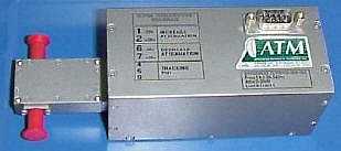 AV06 CVA mounted to a motor drive Motor Drive Outline Drawings: 06 Series, 07 Series, 08 Series |
|
|||||||||||||||||||||||
|
||||||||||||||||||||||||
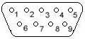
| Motor Characteristics:
1. Motor Control Voltage 2. End Point Indicator * 3. Follower Potentiometer ** |
|
|||||||||||||||||||||||
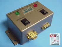
| Narda-MITEQ Optional Control Module:
An External Drive Module part number MCM-001 shown at right, is available for the motor drive as an optional accessory. It includes: |
||||||||||||||||||||||||