• Skip to main content
  • Skip to primary sidebar

Narda-ATM - Microwave RF Components Manufacturer

  • Home
  • Products
    • Coaxial Components
    • Ka-Band Satcom
    • Space Qualified
    • Waveguide Components
  • FAQ
    • Frequently Asked Questions
  • Ordering
    • Catalog
    • Credit Card Order Form
    • Ordering Information
    • Request A Quote
    • Sales Representatives
    • Terms And Conditions
  • Calculators
    • Cable Assy Loss Calculations
    • CF 100 Cable Loss
    • CF 135 Cable Loss
    • CF 160 Cable Loss
    • CF 210 Cable Loss
    • CF 300 Cable Loss
    • CF 500 Cable Loss
    • VSWR Calculator
    • Waveguide Gasket Selection
  • Photos
    • Coaxial Photos
    • Waveguide Photos
    • Flight Waveguide Photos
    • ATM Products In Use
  • Technical
    • Cable Assy Loss Calculation
    • Cable Length Tolerances
    • Mil-Spec References
    • Tech Notes
    • Waveguide Gasket Selection
    • Waveguide Flange Sizes & Types
    • Waveguide Info,Rectangular
    • Waveguide Gasket Info
    • Waveguide Info,Dbl Ridge
    • Waveguide Std. Tolerances
  • About ATM
    • Background
    • Contact ATM
    • News and Videos
    • Privacy Policy
    • Quality Control
    • Satisfaction Survey
You are here: Home / Waveguide Components / Couplers / Power Samplers

Power Samplers

Power Samplers - Waveguide Couplers

Rectangular Waveguide Power Samplers

ATM manufactures in all sizes listed below. They are an excellent and most economical way to sample RF power from the main line in a rectangular waveguide system. 

These rectangular waveguide power samplers cover the full waveguide frequency range with standard coupling values of 30db, 40db, and 50db, however other options are available.

Power samplers are offered with standard RF connectors including SMA and Type-K on some models. Manufactured in aluminum or copper/brass construction. Double ridge waveguide power samplers are also available.

Pressure sealed waveguide power samplers are also available for microwave applications that require sealed systems. Multiple flange and coaxial connector types and configurations are also available. For more information please call us to discuss your needs with our design engineers.

Waveguide Couplers:
Crossguide Directional Couplers
Crossguide Directional Dual Arm
Broadwall Multi-Hole Couplers
Broadwall Multi-Hole Dual Arm
Loop Couplers
Loop Couplers - Double Ridge
Power Samplers - Double Ridge
Short High Directivity Couplers

Coaxial:
Coaxial Couplers

Ka-Band:
Ka-Band Coaxial Couplers
Ka-Band Waveguide Couplers

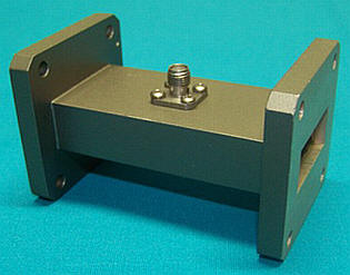
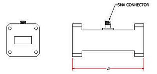
Rectangular Waveguide Power Samplers - SMA Female

Rectangular Waveguide Power Sampler - SMA Female

Rectangular Waveguide Power Sampler - SMA Female - Diagram

TYPICAL SPECIFICATIONS

Electrical
Full waveguide frequency range.
Coupling: 30, 40, 50 dB standard, others available upon request.
VSWR
Primary WR430 thru WR62: 1.05 max (1.08 max for 30dB coupling level)
Primary WR51 thru WR62:   1.10 max (1.15 max for 30dB coupling level)
Secondary Arm: N/A
Nominal Coupling: +/- 1.00dB
Frequency Sensitivity:
     WR430 thru WR62 +/- 1.50dB max
     WR51 thru WR28 +/- 2.0dB max
Mechanical
Standard RF Connectors: SMA female, K female for WR34 and WR28
Body: Aluminum or Brass/Copper.
Connectors: Stainless Steel
Operating Temp: -45°C to 110°C
Finish: Unique corrosion resistant 316 stainless steel epoxy coating IAW MIL-F-14072
Applicable Mil-Specs
General: MIl_DTL-39000, MIL-DTL-3922, AMS-QQ-A-250/11, AMS-QQ-A-225/8, ASTM B209, ASTM B211, ASTM B221, ASTM B152, ASTM B187, ASTM B272, ASTM B16, ASTM B36, ASTM-PRF-39012.
Options
Pressure Sealed Units: Add "/PT" to model number.
Example P/N: 137-350B-dB-2-2
Sealed P/N: 137-350B-dB-2-2/PT
Note: Pressure sealed units will hold 15 psi assuming all waveguide and coax ports are mated and sealed.

 WG Size
Freq. (GHz) Standard
Model No.*
Dim A
(Inches)
Peak Power
(kW)
Average Power
(W)
WR430 1.70 - 2.60 430-350A-dB-2-2 6.00 5000 4500
WR340 2.20 - 3.30 340-350A-dB-2-2 6.00 3700 3500
WR284 2.60 - 3.95 284-350A-dB-6-6 4.00 2200 2000
WR229 3.30 - 4.90 229-350B-dB-2-2 3.00 1300 1200
WR187 3.95 - 5.85 187-350A-dB-6-6 3.00 880 900
WR159 4.90 - 7.05 159-350B-dB-2-2 3.00 740 700
WR137 5.85 - 8.20 137-350B-dB-2-2 3.00 520 500
WR112 7.05 - 10.0 112-350B-dB-6-6 2.00 334 300
WR102 7.00 - 11.0 102-350B-dB-6-6 2.00 262 250
WR90 8.20 - 12.4 90-350A-dB-6-6 2.00 190 220
WR75 10.0 - 15.0 75-350B-dB-6-6 2.00 156 200
WR62 12.4 - 18.0 62-350B-dB-6-6 2.00 112 150
WR51 15.0 - 22.0 51-350B-dB-6-6 2.00 72 120
WR42 18.0 - 26.5 42-350B-dB-6-6 1.75 40 70
WR34 22.0 - 33.0 34-350B-dB-6-6** 1.75 32 70
WR28 26.5 - 40.0 28-350A-dB-6-6** 1.75 21 40
Ordering Information
Waveguide Power Samplers
WR -Mod M -dB -F1 -F2
Example part number:  90 -350 A -30 -6 -6
Waveguide Size: (WR)
WR28 thru WR430 available
         
Basic Model No.: (-Mod)        
Material (M): A=Aluminum, B=Copper/Brass      
Coupling (-dB): 30, 40 or 50 Standard      
Flange 1 (-F1): 1=CPRG, 2=CPRF, 6=Cover, 7=Choke  
Flange 2 (-F2): 1=CPRG, 2=CPRF, 6=Cover, 7=Choke
See ATM Standard Flange page for more info.
 

* The Standard Model Numbers above are the most common parts ordered for size, material and flange. However, these models can easily be altered for your needs by using the Model # code system to the left.

** These units are supplied with 2.9 (K-female type) connectors.

Option: Add /PT to part number for pressure sealed unit to 15 psi.


Primary Sidebar

Search for:

Components Menu

›   Coaxial Components
›   Ka-Band Satcom Components
›   Space Qualified Components
›   Waveguide Components

Latest News and Videos

  • Narda-ATM Re-Certified By NQA for ISO-9001:2015

  • Home
  • Coaxial Components
  • Waveguide Components
  • Ka-Band Components
  • Space Qualified Components

Copyright © 2023 · Narda-ATM