• Skip to main content
  • Skip to primary sidebar

Narda-MITEQ - Microwave RF Components Manufacturer

  • Home
  • About Us
    • Background
    • Contact Narda-MITEQ
    • News and Videos
    • Privacy Policy
    • Quality Control
    • Satisfaction Survey
  • Products
    • Coaxial Components
    • Ka-Band Satcom
    • Space Qualified
    • Waveguide Components
  • FAQ
    • Frequently Asked Questions
  • Ordering
    • Catalog
    • Credit Card Order Form
    • Ordering Information
    • Request A Quote
    • Sales Representatives
    • Terms And Conditions
  • Photos
    • Coaxial Photos
    • Waveguide Photos
    • Flight Waveguide Photos
    • Narda-MITEQ Products In Use
  • Technical
    • Cable Assy Loss Calculation
    • Cable Length Tolerances
    • Mil-Spec References
    • Tech Notes
    • Waveguide Gasket Selection
    • Waveguide Flange Sizes & Types
    • Waveguide Info,Rectangular
    • Waveguide Gasket Info
    • Waveguide Info,Dbl Ridge
    • Waveguide Std. Tolerances
You are here: Home / Waveguide Components / Couplers / Directional Broadwall Multi Hole Dual Arm

Directional Broadwall Multi Hole Dual Arm

Directional Broadwall Multi-Hole Dual Arm Couplers

Dual Arm Multi-hole Directional Couplers

Narda-MITEQ waveguide dual-arm multi-hole directional couplers are similar to our regular Broadwall Multi-hole Directional Couplers, only with the addition of a second coupling output. 

This dual arm broadwall directional coupler covers the full waveguide frequency and is available in either aluminum or copper/brass construction. Single arm broadwall multi-hole directional couplers are also available.

Models are available with standard coupling values of 3db, 6db, 10db, 20db or 30db. Pressure sealed dual arm multi-hole directional couplers are also available for microwave applications that require sealed systems.

Full frequency ranges are covered, and multiple flange and coaxial connector types are available. For more information feel free to call us and discuss your needs with one of our design engineers.

Waveguide Couplers:
Crossguide Directional Couplers
Crossguide Directional Dual Arm
Broadwall Multi-Hole Couplers
Loop Couplers
Loop Couplers - Double Ridge
Power Samplers
Power Samplers - Double Ridge
Short High Directivity Couplers

Coaxial:
Coaxial Couplers

Ka-Band:
Ka-Band Coaxial Couplers
Ka-Band Waveguide Couplers

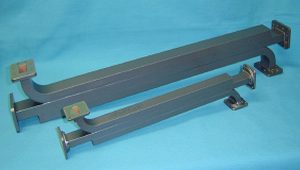
GENERAL SPECIFICATIONS ( All Options )
DUAL ARM BROADWALL DIRECTIONAL COUPLERS

Electrical
Std.  Coupling Values:   3, 6, 10, 20, 30dB
Nominal Coupling:   +/- 0.70 (+/-1.0 for WR42, WR34, WR28)
Freq. Sensitivity:   +/- 0.60 (+/-0.75 for WR42, WR34, WR28)
VSWR
Primary Line max:   1.05 (1.10 for WR62, WR51, WR42, WR34, WR28)
Secondary W/G Line max:   1.10 (1.15 for WR42, WR34, WR28)
Secondary Coax Line max:   1.25 (1.4 for WR42, WR34, WR28)
Directivity:   40 dB typical, 30 min
RF Connectors: SMA Type-N, standard

Mechanical
Size:  See Tables
Body: Aluminum/Copper-Brass
Coax Connectors: Stainless Steel
Finish: Unique corrosion resistant 316 stainless steel epoxy coating IAW MIL-F-14072.
Applicable Mil-Specs
General:
Product Specific:
Options
Pressure Sealed Units: Add "/PT" to model number.
Example P/N: 284-304A-30F-30R-6-6-6-6
Sealed P/N: 284-304A-30F-30R-6-6-6-6/PT
Note: Pressure sealed units will hold 15 psi assuming all waveguide and coax ports are mated and sealed.


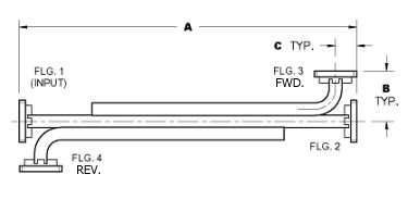
4 Waveguide Port - Dual Arm Broadwall Directional Coupler
Series 304 Dual Arm Waveguide Broadwall Directional Coupler Series 304 Waveguide Broadwall Directional Coupler - Diagram
 WG Size Freq. (GHz) Standard
Model No.*
Dim. A
inches
Dim. B
inches
Dim. C
inches
WR284 2.60 - 3.95 284-304A-dBF-dBR-6-6-6-6 50.25 6.00 2.66
WR229 3.30 - 4.90 229-304B-dB-dBR-2-2-2-2 42.00 6.81 1.84
WR187 3.95 - 5.85 187-304A-dBF-dBR-6-6-6-6 34.62 6.44 1.81
WR159 4.90 - 7.05 159-304B-dBF-dBR-2-2-2-2 32.50 5.25 1.56
WR137 5.85 - 8.20 137-304B-dBF-dBR-2-2-2-2 26.50 3.06 1.56
WR112 7.05 - 10.0 112-304B-dBF-dBR-6-6-6-6 18.62 3.06 1.56
WR90 8.20 - 12.4 90-304A-dBF-dBR-6-6-6-6 16.68 2.50 1.50
WR75 10.0 - 15.0 75-304B-dBF-dBR-6-6-6-6 15.00 2.50 1.25
WR62 12.4 - 18.0 62-304B-dBF-dBR-6-6-6-6 13.75 2.18 0.66
WR51 15.0 - 22.0 51-304B-dBF-dBR-6-6-6-6 11.50 1.25 0.66
WR42 18.0 - 26.5 42-304B-dBF-dBR-6-6-6-6 9.50 1.25 0.75
WR34 22.0 - 33.0 34-304B-dBF-dBR-6-6-6-6 9.00 1.25 0.75
WR28 26.5 - 40.0 28-304A-dBF-dBR-6-6-6-6 8.00 1.12 0.75
Ordering Information
Broadwall Directional Couplers

Dual Arm 4-Ports
WR -Mod M -dBF -dBR -F1 -F2 -F3 -F4
Example part number:  90 -304 A -30 -30 -6 -6 -6 -6
Waveguide Size: (WR)
WR28 thru WR650 available
               
Basic Model No.: (-Mod)              
Material (M): A=Aluminum, B=Copper/Brass            
Fwd. Coupling (-dBF): 3, 6, 10, 20 or 30 std          
Rev. Coupling (-dBR): 3, 6, 10, 20 or 30 std        
Flange 1 (-F1): 1=CPRG, 2=CPRF, 6=Cover, 7=Choke       
Flange 2 (-F2): 1=CPRG, 2=CPRF, 6=Cover, 7=Choke    
Flange 3 (-F3): 1=CPRG, 2=CPRF, 6=Cover, 7=Choke  
Flange 4 (-F4): 1=CPRG, 2=CPRF, 6=Cover, 7=Choke
See Narda-MITEQ Standard Flange page for more info.

* The Standard Model Numbers above are the most common parts ordered for size, material and flange. However, these models can easily be altered for your needs by using the Model # code system to the left.

Option: Add /PT to part number for pressure sealed unit to 15 psi.


Primary Sidebar

Search for:
NardaMITEQ.com

Components Menu

›   Coaxial Components
›   Ka-Band Satcom Components
›   Space Qualified Components
›   Waveguide Components

Latest News and Videos

  • Narda-MITEQ Re-Certified By NQA for ISO-9001:2015

  • Home
  • Coaxial Components
  • Waveguide Components
  • Ka-Band Components
  • Space Qualified Components

Copyright © 2025 · Narda-MITEQ