• Skip to main content
  • Skip to primary sidebar

Narda-ATM - Microwave RF Components Manufacturer

  • Home
  • Products
    • Coaxial Components
    • Ka-Band Satcom
    • Space Qualified
    • Waveguide Components
  • FAQ
    • Frequently Asked Questions
  • Ordering
    • Catalog
    • Credit Card Order Form
    • Ordering Information
    • Request A Quote
    • Sales Representatives
    • Terms And Conditions
  • Calculators
    • Cable Assy Loss Calculations
    • CF 100 Cable Loss
    • CF 135 Cable Loss
    • CF 160 Cable Loss
    • CF 210 Cable Loss
    • CF 300 Cable Loss
    • CF 500 Cable Loss
    • VSWR Calculator
    • Waveguide Gasket Selection
  • Photos
    • Coaxial Photos
    • Waveguide Photos
    • Flight Waveguide Photos
    • ATM Products In Use
  • Technical
    • Cable Assy Loss Calculation
    • Cable Length Tolerances
    • Mil-Spec References
    • Tech Notes
    • Waveguide Gasket Selection
    • Waveguide Flange Sizes & Types
    • Waveguide Info,Rectangular
    • Waveguide Gasket Info
    • Waveguide Info,Dbl Ridge
    • Waveguide Std. Tolerances
  • About ATM
    • Background
    • Contact ATM
    • News and Videos
    • Privacy Policy
    • Quality Control
    • Satisfaction Survey
You are here: Home / Waveguide Components / Couplers / Loop Couplers, Double Ridge

Loop Couplers, Double Ridge

Double Ridge Waveguide Loop Couplers

Waveguide Double Ridge Loop Couplers

ATM manufactures Loop couplers covering a wide frequency range.  Multiple flange and Coaxial connector types and configurations are available. 

Our double ridge waveguide loop couplers are ideal for RF microwave applications where high power sensing is desired. These single arm waveguide loop couplers are available with SMA or Type-N connectors. Multi arm models are also available.

Double ridge waveguide loop couplers cover the full waveguide frequency with standard coupling values of 30db, 40db, 50db, and 60db, however other options are available upon request.

Rectangular waveguide loop couplers are also available. Pressure sealed double ridge loop couplers are also available for microwave applications that require sealed systems. For more information feel free to call us and discuss your needs with one of our design engineers.

Waveguide Couplers:
Crossguide Directional Couplers
Crossguide Directional Dual Arm
Broadwall Multi-Hole Couplers
Broadwall Multi-Hole Dual Arm
Loop Couplers
Power Samplers
Power Samplers - Double Ridge
Short High Directivity Couplers

Coaxial:
Coaxial Couplers

Ka-Band:
Ka-Band Coaxial Couplers
Ka-Band Waveguide Couplers

GENERAL SPECIFICATIONS
DOUBLE RIDGE LOOP COUPLERS
Double Ridge Waveguide Loop Couplers - SMA


  • Full waveguide frequency range
  • Ideal for High Power Sensing
  • Single Arm standard
  • Multi-Arm available

Electrical
VSWR:
Primary: 1.07 Max
Coax: 1.50 Max (SMA F), 1.50 Max (TypeN F)
Coupling: 30, 40, 50, or 60dB std., others available upon request.
Nominal Coupling: +/- 1.00 dB
Frequency Sensitivity: +/- 1.50dB max.
Directivity: 12dB min., 15dB typ.
RF Connectors: SMA-F, Type-N-F (Standard)
Mechanical
Body: Aluminum ONLY
Connectors: Stainless Steel
Operation Temp:
Finish: Unique corrosion resistant 316
stainless steel epoxy coating IAW MIL-F-14072.
Applicable Mil-Specs
General:
Product Specific:
Options
Pressure Sealed Units: Add "/PT" to model number.
Example P/N: 580-307-dB-C3-C3
Sealed P/N: 580-307-dB-C3-C3/PT
Note: Pressure sealed units will hold 15 psi assuming all waveguide and coax ports are mated and sealed.


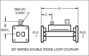
Double Ridge Waveguide Loop Coupler - SMA (F)
Double Ridge Waveguide Loop Couplers - SMA
Series 307 Double Ridge Waveguide Loop Coupler
WG Size Freq. (GHz) Basic Model No.* RF Power
Avg Watts
Peak Power
(KW)
Dim A
(Inches)
Dim B
(Inches)
Dim C
(Inches)

Outline
Drawings
WRD750 7.50 - 18.0 750-307-dB-C3-C3 1550 12 2.5 0.9 0.63  
WRD650 6.50 - 18.0 650-307-dB-C3-C3 1400 11 2.5 0.9 0.63 Dwg
WRD580 5.85 - 14.5 580-307-dB-C3-C3 1750 15 3.0 1.0 0.88 Dwg
WRD475 4.75 - 11.0 475-307-dB-C3-C3 3000 35 3.5 1.1 1.13  
WRD350 3.50 - 8.20 350-307-dB-C3-C3 6000 60 3.0 1.1 0.88 Dwg
WRD250 2.60 - 7.80 250-307-dB-C3-C3 10000 60 3.5 1.0 1.12 Dwg
Ordering Information
Double Ridge Waveguide
Loop Couplers - SMA (F)
WRD -Mod -dB -F1 -F2
Example part number:  750 -307 -30 -C3 -C3
Waveguide Size: (WRD)
WRD250 thru WRD750 available
       
Basic Model No.: (-Mod)      
Coupling (-dB): 30, 40, 50 or 60 dB Standard **    
Flange 1 (-F1): C=Cover, G= Groove
1=alternate holes, 2=all tapped holes, 3=all thru holes
   
Flange 2 (-F2): C=Cover, G= Groove
1=alternate holes, 2=all tapped holes, 3=all thru holes
See ATM Standard Flange page for more info.

* The Standard Model Numbers above are the most common parts ordered for size, material and flange. However, these models can easily be altered for your needs by using the Model # code system to the left.

** The customer must choose the coupling value appropriate for the application (30, 40, 50 or 60dB)

Option: Add /PT to part number for pressure sealed unit to 15 psi.

For a dual unit modify the P/N by adding a 'D' to the end of the basic model #, the direction of the coupling of both the primary and secondary arms.
Example:
750-307-dB=C3-C3 becomes: 750-307D-dBF-dBR-C3-C3.
(Where F=forward coupling and R=reverse coupling)


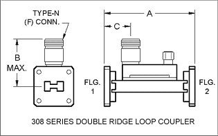
Double Ridge Waveguide Loop Coupler - Type N (F)
Double Ridge Waveguide Loop Couplers - SMA
Series 308 Doublr Ridge Loop Coupler - Type-N - Diagram
WG Size Freq. (GHz) Basic Model No.* RF Power
Avg Watts
Peak Power
(KW)
Dim A
(Inches)
Dim B
(Inches)

Dim C
(Inches)

Outline
Drawings
WRD750 7.50 - 18.0 750-308-dB-C3-C3 1550 12 2.5 0.8 0.63  
WRD650 6.50 - 18.0 650-308-dB-C3-C3 1400 11 2.5 0.8 0.63  
WRD580 5.85 - 14.5 580-308-dB-C3-C3 1750 15 3.0 0.8 0.88  
WRD475 4.75 - 11.0 475-308-dB-C3-C3 3000 35 3.5 0.8 1.13  
WRD350 3.50 - 8.20 350-308-dB-C3-C3 6000 60 3.0 0.8 1.13  
WRD250 2.60 - 7.80 250-308-dB-C3-C3 10000 60 3.5 1.63 1.12 Dwg
Ordering Information
Double Ridge Waveguide
Loop Couplers - Type-N (F)
WRD -Mod -dB -F1 -F2
Example part number:  750 -308 -30 -C3 -C3
Waveguide Size: (WRD)
WRD250 thru WRD750 available
       
Basic Model No.: (-Mod)      
Coupling (-dB): 30, 40, 50 or 60 dB Standard **    
Flange 1 (-F1): C=Cover, G= Groove
1=alternate holes, 2=all tapped holes, 3=all thru holes
   
Flange 2 (-F2): C=Cover, G= Groove
1=alternate holes, 2=all tapped holes, 3=all thru holes
See ATM Standard Flange page for more info.

* The Standard Model Numbers above are the most common parts ordered for size, material and flange. However, these models can easily be altered for your needs by using the Model # code system to the left.

** Customer must choose the coupling value appropriate for the application (30, 40, 50 or 60dB)

Option: Add /PT to part number for pressure sealed unit to 15 psi.

For a dual unit modify the P/N by adding a 'D' to the end of the basic model #, the direction of the coupling of both the primary and secondary arms.
Example:
750-308-dB=C3-C3 becomes: 750-308D-dBF-dBR-C3-C3.
(Where F=forward coupling and R=reverse coupling)


Primary Sidebar

Search for:

Components Menu

›   Coaxial Components
›   Ka-Band Satcom Components
›   Space Qualified Components
›   Waveguide Components

Latest News and Videos

  • Narda-ATM Re-Certified By NQA for ISO-9001:2015

  • Home
  • Coaxial Components
  • Waveguide Components
  • Ka-Band Components
  • Space Qualified Components

Copyright © 2023 · Narda-ATM