• Skip to main content
  • Skip to primary sidebar

Narda-ATM - Microwave RF Components Manufacturer

  • Home
  • Products
    • Coaxial Components
    • Ka-Band Satcom
    • Space Qualified
    • Waveguide Components
  • FAQ
    • Frequently Asked Questions
  • Ordering
    • Catalog
    • Credit Card Order Form
    • Ordering Information
    • Request A Quote
    • Sales Representatives
    • Terms And Conditions
  • Calculators
    • Cable Assy Loss Calculations
    • CF 100 Cable Loss
    • CF 135 Cable Loss
    • CF 160 Cable Loss
    • CF 210 Cable Loss
    • CF 300 Cable Loss
    • CF 500 Cable Loss
    • VSWR Calculator
    • Waveguide Gasket Selection
  • Photos
    • Coaxial Photos
    • Waveguide Photos
    • Flight Waveguide Photos
    • ATM Products In Use
  • Technical
    • Cable Assy Loss Calculation
    • Cable Length Tolerances
    • Mil-Spec References
    • Tech Notes
    • Waveguide Gasket Selection
    • Waveguide Flange Sizes & Types
    • Waveguide Info,Rectangular
    • Waveguide Gasket Info
    • Waveguide Info,Dbl Ridge
    • Waveguide Std. Tolerances
  • About ATM
    • Background
    • Contact ATM
    • News and Videos
    • Privacy Policy
    • Quality Control
    • Satisfaction Survey
You are here: Home / Waveguide Components / Couplers / Power Samplers, Double Ridge

Power Samplers, Double Ridge

Double Ridge Waveguide RF Power Samplers

Double Ridge Waveguide Power Samplers

ATM manufactures in all double ridge waveguide sizes listed below. They are an excellent and most economical way to sample RF Power from the main line in a double ridge waveguide system. 

These double ridge waveguide power samplers cover the full waveguide frequency range with standard coupling values of 30db, 40db, and 50db, however other options are available.

Power samplers are offered with standard RF connectors including SMA and Type-K on some models. Manufactured in aluminum construction. Rectangular waveguide power samplers are also available.

Pressure sealed double ridge waveguide power samplers are also available for rf applications that require sealed systems. Multiple flange and coaxial connector types and configurations are also available. For more information please call us to discuss your needs with our design engineers.

Waveguide Couplers:
Crossguide Directional Couplers
Crossguide Directional Dual Arm
Broadwall Multi-Hole Couplers
Broadwall Multi-Hole Dual Arm
Loop Couplers
Loop Couplers - Double Ridge
Power Samplers
Short High Directivity Couplers

Coaxial:
Coaxial Couplers

Ka-Band:
Ka-Band Coaxial Couplers
Ka-Band Waveguide Couplers

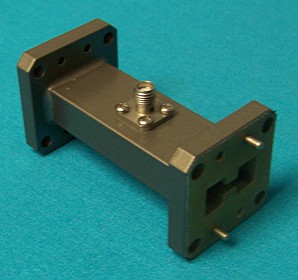
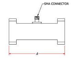
Double Ridge Waveguide Power Samplers - SMA Female

Double Ridge Waveguide Power Sampler - SMA

Double Ridge Waveguide Power Sampler - SMA - Diagram

TYPICAL SPECIFICATIONS

Electrical
Full waveguide frequency range.
Coupling: 30, 40, 50 dB standard, others available upon request.
VSWR Primary: 1.08 max (1.15 max for 30dB coupling level)
SMA port: N/A

Nominal Coupling: +/- 1.00dB
Frequency Sensitivity: +/- 3 dB max.
Mechanical
Standard RF Connectors: SMA female, K female for WRD180
Body: Aluminum
Connectors: Stainless Steel
Operating Temp: -55°C to +110°C
Finish: Unique corrosion resistant 316 stainless steel epoxy coating IAW MIL-F-14072
Applicable Mil-Specs
General: MIl_DTL-39000, MIL-DTL-3922, AMS-QQ-A-250/11, AMS-QQ-A-225/8, ASTM B209, ASTM B211, ASTM B221, ASTM-PRF-39012.
Options
Pressure Sealed Units: Add "/PT" to model number.
Example P/N: 580-350-dB-C1-C1
Sealed P/N: 580-350-dB-C1-C1/PT
Note: Pressure sealed units will hold 15 psi assuming all waveguide and coax ports are mated and sealed.

WG Size    Freq. (GHz) Standard
Model No.*
Dim A
(
Inches)  
Peak Power
(kW)
Average Power
(W)
WRD200 2.00 - 4.80 200-350-dB-C1-C1 2.50 30 2800
WRD250 2.60 - 7.80 250-350-dB-C1-C1 2.50 27 2350
WRD350 3.50 - 8.20 350-350-dB-C1-C1 2.30 26 2250
WRD475 4.80 - 11.0 475-350-dB-C1-C1 2.00 28 1800
WRD580 5.80 - 16.0 580-350-dB-C1-C1 2.00 22 900
WRD650 6.50 - 18.0 650-350-dB-C1-C1 2.00 10 480
WRD750 7.50 - 18.0 750-350-dB-C1-C1 2.00 7 330
WRD180 18.0 - 40.0 180-350-dB-C1-C1** 1.50 8 420
Ordering Information
Double Ridge Waveguide
Power Samplers - SMA
WRD -Mod -dB -F1 -F2
Example part number:  750 -350 -30 -C1 -C1
Waveguide Size: (WRD)
WRD200 thru WRD180 available
       
Basic Model No.: (-Mod)      
Coupling (-dB): 30, 40 or 50 dB Standard    
Flange 1 (-F1): C1 (Alternate), C2 (All tapped), C3 (All clear)    
Flange 2 (-F2): C1 (Alternate), C2 (All tapped), C3 (All clear)
See ATM Standard Flange page for more info.

* The Standard Model Numbers above are the most common parts ordered for size, material and flange. However, these models can easily be altered for your needs by using the Model # code system to the left.

** These units are supplied with 2.9 (K-female type) connectors.

Option: Add /PT to part number for pressure sealed unit to 15 psi.


Primary Sidebar

Search for:

Components Menu

›   Coaxial Components
›   Ka-Band Satcom Components
›   Space Qualified Components
›   Waveguide Components

Latest News and Videos

  • Narda-ATM Re-Certified By NQA for ISO-9001:2015

  • Home
  • Coaxial Components
  • Waveguide Components
  • Ka-Band Components
  • Space Qualified Components

Copyright © 2023 · Narda-ATM