| Waveguide Fixed High Power Precision Attenuators | |||||||
|---|---|---|---|---|---|---|---|
|
|
GENERAL SPECIFICATIONS | ||||||
|
Electrical |
|||||||
| WG Size | Freq. (GHz) | VSWR | Power Watt |
Standard Model No.* |
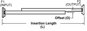
Dimensions | Outline Drawings |
|
| Length (L) Inches |
Offset (O) Inches |
||||||
| WR430 | 1.70 - 2.60 | 1.15 | 1200 | 430-630HPA-dB-2-2 | 54.0 | 2.230 | |
| WR340 | 2.20 - 3.30 | 1.15 | 1200 | 340-630HPA-dB-2-2 | 42.0 | 1.780 | |
| WR284 | 2.60 - 3.95 | 1.15 | 1200 | 284-630HPA-dB-6-6 | 33.0 | 1.460 | Dwg |
| WR229 | 3.30 - 4.90 | 1.15 | 1000 | 229-630HPA-dB-2-2 | 27.0 | 1.209 | Dwg |
| WR187 | 3.95 - 5.85 | 1.15 | 750 | 187-630HPA-dB-6-6 | 24.0 | 0.936 | |
| WR159 | 4.9 - 7.05 | 1.15 | 625 | 159-630HPA-dB-2-2 | 24.0 | 0.859 | |
| WR137 | 5.85 - 8.20 | 1.15 | 500 | 137-630HPA-dB-2-2 | 22.5 | 0.686 | |
| WR112 | 7.05 - 10.0 | 1.15 | 425 | 112-630HPA-dB-6-6 | 16.0 | 0.561 | |
| WR90 | 8.20 - 12.4 | 1.15 | 225 | 90-630HPA-dB-6-6 | 14.5 | 0.450 | |
| WR75 | 10.0 - 15.0 | 1.15 | 200 | 75-630HPA-dB-6-6 | 13.5 | 0.425 | |
| WR62 | 12.4 - 18.0 | 1.15 | 100 | 62-630HPA-dB-6-6 | 11.5 | 0.351 | |
| WR51 | 15.0 - 22.0 | 1.15 | 100 | 51-630HPA-dB-6-6 | 11.5 | 0.295 | |
| WR42 | 18.0 - 26.5 | 1.15 | 100 | 42-630HPA-dB-6-6 | 9.5 | 0.210 | Dwg |
| WR34 | 22.0 - 33.0 | 1.15 | 75 | 34-630HPA-dB-6-6 | 9.5 | 0.210 | Dwg |
| WR28 | 26.5 - 40.0 | 1.15 | 75 | 28-630HPA-dB-6-6 | 9.0 | 0.180 | Dwg |
|
* Insert desired attenuation value (10, 20, 30, 40, or 50dB attenuator ) in the model number where dB is listed |
|||||||
|
* The Standard Model Numbers above are the most common parts ordered for size, material and flange. However, these models can easily be altered for your needs by using the Model # code system to the left. ** Choose the attenuation value appropriate for application (10dB, 20dB, 30dB, 40dB, or 50dB attenuator ) and insert it in the model number where dB is listed. |
||||||||||||||||||||||||||||||||||||||||||||||||||||||||
| Example P/N: 284-630HPA-20-6-6 is: WG size WR284 High Power Attenuator / Aluminum / 20dB Attenuation / Cover Flange / Cover Flange* |
|||||||||||||||||||||||||||||||||||||||||||||||||||||||||