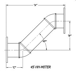
| Dual 45° Custom Mitered E & H Bends - Rectangular Waveguide | |||||
|---|---|---|---|---|---|
|
|||||
| WG Size | Freq. (GHz) | 45° HH Miter* |
45° EE Miter* | ||
| WR284 | 2.60 - 3.95 | 284-45HHA-6.60 x 1.70 x 2.48-6-6 | 284-45EEA-5.34 x 1.08 x 2.13-6-6 | ||
| WR229 | 3.30 - 4.90 | 229-45HHB-7.22 x 1.76 x 2.73-2-2 | 229-45EEB-5.96 x 1.56 x 2.20-2-2 | ||
| WR187 | 3.95 - 5.85 | 187-45HHA-7.25 x 2.13 x 2.56-6-6 | 187-45EEA-5.37 x 1.19 x 2.09-6-6 | ||
| WR137 | 5.85 - 8.20 | 137-45HHB-5.62 x 0.96 x 2.33-2-2 | 137-45EEB-4.63 x 0.68 x 1.98-2-2 | ||
| WR112 | 7.05 - 10.0 | 112-45HHB-5.36 x 1.30 x 2.03-6-6 | 112-45EEB-4.25 x 0.81 x 1.72-6-6 | ||
| WR102 | 7.00 - 11.0 | 102-45HHA-5.36 x 1.30 x 2.03-6-6 | 102-45EE-4.25 x 0.81 x 1.72-6-6 | ||
| WR90 | 8.20 - 12.4 | 90-45HHA-4.84 x 0.94 x 1.95-6-6 | 90-45EEA-4.05 x 0.69 x 1.68-6-6 | ||
| WR75 | 10.0 - 15.0 | 75-45HHB-4.84 x 0.94 x 1.95-6-6 | 75-45EEB-4.02 x 0.61 x 1.70-6-6 | ||
| WR62 | 12.4 - 18.0 | 62-45HHB-2.38 x 0.64 x 0.87-6-6 | 62-45EEB-2.01 x 0.51 x 0.75-6-6 | ||
| WR51 | 15.0 - 22.0 | 51-45HHB-2.68 x 1.06 x 0.81-6-6 | 51-45EEB-1.89 x 0.51 x 0.69-6-6 | ||
| WR42 | 18.0 - 26.5 | 42-45HHB-1.90 x 0.48 x 0.71-6-6 | 42-45EEB-1.62 x 0.46 0.58-6-6 | ||
 Order Worksheet
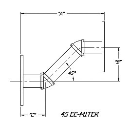
|
* The Standard Model Numbers above are the most common parts ordered for size, material and flange. However, these models can easily be altered for your needs by using the Model # code system to the left. ** Legs A, B and C available in other sizes. Consult factory for more information. |
||||||||||||||||||||||||||||||||||||||||||||||||||||||||
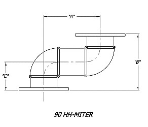
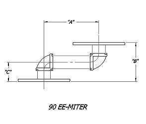
| Dual 90° Custom Mitered E & H Bends - Rectangular Waveguide | |||||
|---|---|---|---|---|---|
|
|
|||||
| WG Size | Freq. (GHz) | 90° HH Miter* | 90° EE Miter* | ||
| WR284 | 2.60 - 3.95 | 284-90HHA–3.38 x 8.00 x 4.00-6-6 | 284-90EEA–1.88 x 7.50 x 3.75-6-6 | ||
| WR229 | 3.30 - 4.90 | 229-90HHB–2.81 x 6.00 x 3.00-2-2 | 229-90EEB–1.75 x 4.42 x 2.21-2-2 | ||
| WR187 | 3.95 - 5.85 | 187-90HHA– 2.44 x 6.00 x 3.00-6-6 | 187-90EEA-1.50 x 3.74 x 1.87-6-6 | ||
| WR159 | 4.09 - 7.05 | 159-90HHB-2.31 x 6.00 x 3.00-2-2 | 159-90EEB-1.44 x 3.50 x 1.75-2-2 | ||
| WR137 | 5.85 - 8.20 | 137-90HHB-2.00 x 6.00 x 3.00-2-2 | 137-90EEB-1.19 x 3.64 x 1.82-2-2 | ||
| WR112 | 7.05 - 10.0 | 112-90HHB–1.63 x 4.00 x 2.00-6-6 | 112-90EEB-1.00 x 3.20 x 1.60-6-6 | ||
| WR102 | 7.00 - 11.0 | 102-90HHA– 1.63 x 4.00 x 2.00-6-6 | 102-90EEA–1.00 x 2.94 x 1.47-6-6 | ||
| WR90 | 8.20 - 12.4 | 90-90HHA-1.50 x 4.00 x 2.00-6-6 | 90-90EEA-1.00 x 2.68 x 1.34-6-6 | ||
| WR75 | 10.0 - 15.0 | 75-90HHB-1.31 x 4.00 x 2.00-6-6 | 75-90EEB-1.00 x 2.32 x 1.16-6-6 | ||
| WR62 | 12.4 - 18.0 | 62-90HHB-1.06 x 3.00 x 1.50-6-6 | 62-90EEB-0.81 x 2.00 x 1.00-6-6 | ||
| WR51 | 15.0 - 22.0 | 51-90HHB-0.94 x 3.00 x 1.50-6-6 | 51-90EEB-0.69 x 1.90 x 0.95-6-6 | ||
| WR42 | 18.0 - 26.5 | 42-90HHB-.094 x 2.00 x 1.00-6-6 | 42-90EEB-0.63 x 1.54 x 0.77-6-6 | ||
| WR34 | 22.0 - 33.0 | 34-90HHB-0.88 x 2.00 x 1.00-6-6 | 34-90EEB-0.63 x 1.54 x 0.77-6-6 | ||
| WR28 | 26.5 - 40.0 | 28-90HHB-0.75 x 2.00 x 1.00-6-6 | 28-90EEB-0.63 x 1.54 x 0.77-6-6 | ||
 Order Worksheet
|
* The Standard Model Numbers above are the most common parts ordered for size, material and flange. However, these models can easily be altered for your needs by using the Model # code system to the left. ** Legs A, B and C available in other sizes. Consult factory for more information. |
||||||||||||||||||||||||||||||||||||||||||||||||||||||||
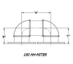
| Dual 180° Custom Mitered E & H Bends - Rectangular Waveguide | |||||
|---|---|---|---|---|---|
|
|||||
| WG Size | Freq. (GHz) | 180° HH Miter* | 180° EE Miter* | ||
| WR284 | 2.60 - 3.95 | 284-180HHA-5.56 x 6.00 x 6.00-6-6 | 284-180EEA-5.56 x 6.00 x 6.00-6-6 | ||
| WR229 | 3.30 - 4.90 | 229-180HHB-4.13 x 4.00 x 4.00-2-2 | 229-180EEB-4.13 x 4.00 x 4.00-2-2 | ||
| WR187 | 3.95 - 5.85 | 187-180HHA-3.88 x 3.00 x 3.00-6-6 | 187-180EEA-3.88 x 3.00 x 3.00-6-6 | ||
| WR159 | 4.09 - 7.05 | 159-180HHB-3.63 x 2.50 x 2.50-2-2 | 159-180EEB-3.63 x 2.50 x 2.50-2-2 | ||
| WR137 | 5.85 - 8.20 | 137-180HHB-3.38 x 2.50 x 2.50-2-2 | 137-180EEB-3.38 x 2.50 x 2.50-2-2 | ||
| WR112 | 7.05 - 10.0 | 112-180HHB-2.69 x 2.00 x 2.00-6-6 | 112-180EEB-2.69 x 2.00 x 2.00-6-6 | ||
| WR102 | 7.00 - 11.0 | 102-180HHA-2.69 x 2.00 x 2.00-6-6 | 102-180EEA-2.69 x 2.00 x 2.00-6-6 | ||
| WR90 | 8.20 - 12.4 | 90-180HHA-2.25 x 2.00 x 2.00-6-6 | 90-180EEA-2.25 x 2.00 x 2.00-6-6 | ||
| WR75 | 10.0 - 15.0 | 75-180HHB-1.88 x 1.75 x 1.75-6-6 | 75-180EEB-1.88 x 1.75 x 1.75-6-6 | ||
| WR62 | 12.4 - 18.0 | 62-180HHB-1.38 x 1.75 x 1.75-6-6 | 62-180EEB-1.38 x 1.75 x 1.75-6-6 | ||
| WR51 | 15.0 - 22.0 | 51-180HHB-1.38 x 1.50 x 1.50-6-6 | 51-180EEB–1.38 x 1.50 x 1.50-6-6 | ||
| WR42 | 18.0 - 26.5 | 42-180HHB-0.94 x 1.00 x 1.00-6-6 | 42-180EEB-0.94 x 1.00 x 1.00-6-6 | ||
| WR34 | 22.0 - 33.0 | 34-180HHB-0.94 x 1.00 x 1.00-6-6 | 34-180EEB-0.94 x 1.00 x 1.00-6-6 | ||
| WR28 | 26.5 - 40.0 | 28-180HHB-0.75 x 1.00 x 1.00-6-6 | 28-180EEB-0.81 x 1.00 x 1.00-6-6 | ||
 Order Worksheet
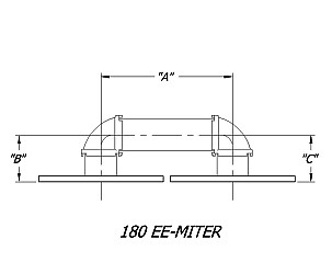
|
* The Standard Model Numbers above are the most common parts ordered for size, material and flange. However, these models can easily be altered for your needs by using the Model # code system to the left. ** Legs A, B and C available in other sizes. Consult factory for more information. |
||||||||||||||||||||||||||||||||||||||||||||||||||||||||