• Skip to main content
  • Skip to primary sidebar

Narda-ATM - Microwave RF Components Manufacturer

  • Home
  • Products
    • Coaxial Components
    • Ka-Band Satcom
    • Space Qualified
    • Waveguide Components
  • FAQ
    • Frequently Asked Questions
  • Ordering
    • Catalog
    • Credit Card Order Form
    • Ordering Information
    • Request A Quote
    • Sales Representatives
    • Terms And Conditions
  • Calculators
    • Cable Assy Loss Calculations
    • CF 100 Cable Loss
    • CF 135 Cable Loss
    • CF 160 Cable Loss
    • CF 210 Cable Loss
    • CF 300 Cable Loss
    • CF 500 Cable Loss
    • VSWR Calculator
    • Waveguide Gasket Selection
  • Photos
    • Coaxial Photos
    • Waveguide Photos
    • Flight Waveguide Photos
    • ATM Products In Use
  • Technical
    • Cable Assy Loss Calculation
    • Cable Length Tolerances
    • Mil-Spec References
    • Tech Notes
    • Waveguide Gasket Selection
    • Waveguide Flange Sizes & Types
    • Waveguide Info,Rectangular
    • Waveguide Gasket Info
    • Waveguide Info,Dbl Ridge
    • Waveguide Std. Tolerances
  • About ATM
    • Background
    • Contact ATM
    • News and Videos
    • Privacy Policy
    • Quality Control
    • Satisfaction Survey
You are here: Home / Waveguide Components / Arc Detector

Arc Detector

Arc Detectors For Waveguide

Waveguide Arc Detectors

ATM manufactures Waveguide Arc Detectors covering the full frequency range for Rectangular Waveguides, with multiple flange configurations available.  Waveguide Arc Detectors are used to detect arcs inside high power waveguide systems.

For more information call us and discuss your Arc Detector requirements with one of our design engineers.

See Also:
Waveguide Components Menu

Ka-Band:
Ka-Band Waveguide Arc Detectors

 Waveguide Arc Detectors

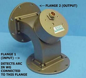
Atm's series of Arc Detectors are opto-electric devices which detect visible arcs in high-power microwave waveguides.  They are normally mounted between the output flange of the microwave source and the transmission line in a 90 degree E-plane bend configuration. Other configurations may be manufactured upon special request. ATM offers Arc Detectors in waveguide sizes ranging from WR28 - WR284.  Please call us and discuss your needs with one of our design engineers.

How ATM Waveguide Arc Detectors work electrically:

  • In the base model of ATM's Arc Detector, +15 VDC at 25mA is applied to pin A to arm the device.  When armed, the arc detector will develop TTL 1 (2.4 - 5.0 volts, 3.5 volts typical) on the output, Pin D.  In response to a visible arc in the waveguide facing the detector device (input flange 1), Pin D will have an output of TTL 0 ( 0-0.8 volts ).  Pin D will remain at this level until the arc in the waveguide is no longer present.
  • The Arc will automatically re-arm when the waveguide is no longer illuminated.
  • Pins E and F (case ground) are ground connections.
Waveguide Arc Detector
GENERAL SPECIFICATIONS
(WAVEGUIDE ARC DETECTOR STANDARD OPTIONS)
 Input Power: 15+ VDC at 25mA
 Pressure Sealed to: 30 PSI
 Output Voltage
 
Armed: TTL 1
(2.4 - 5.0 volts, 3.5 volts typical)
Fault/Fired: TTL 0
(0 - 0.8 volts)
 Response Time: less than 10 µsec.

Arc Detector Options:

  • A - Input Voltage:  Input voltage at Pin A is +28VDC at 40 mA, Output voltage TTL 1(2.4 - 5.0 volts, 3.5 volts typical)
  • B - Latching Reset Capability (+5VDC):  After being triggered by an arc, the output will remain at less than one volt until the Arc Detector is manually reset.  This is accomplished by bringing Pin C to +5VDC (TTL) momentarily, then returned to case ground.
  • BB - Latching Reset Capability (Open Circuit):  After being triggered by an arc, the output will remain at less than one volt until the Arc Detector is manually reset.  This is accomplished by removing pin C from case ground to an "open circuit" momentarily, then returned to case ground.
  • C - Self test:  To test the Arc Detector's triggering/latching ability, +5 VDC is applied to pin B.  Current required is 20mA
  • D - Output Voltage:  Output voltage is +15 VDC.  This option requires choosing option A, +28 VDC input,  The fired voltage is less than 1 volt.

Note: For any of the options shown above add the appropriate letter to the end of the model number.  It is possible to add more than one option. Example P/N:  137-ARCE-A-2-2 becomes: 137-ARCE-A-2-2/AB when options A & B are desired.


Waveguide Arc Detector - Standard Models
WG Size Freq. (GHz) VSWR
(max)
Insertion Loss
(max)
Peak Power
(max)
Model No.* Outline
Drawing
WR284 2.60 - 3.95 1.10 0.05 1 MW 284-ARCE-A-6-6 Dwg
WR229 3.30 - 4.90 1.10 0.05 900 KW 229-ARCE-A-2-2 Dwg
WR187 3.95 - 5.85 1.10 0.05 800 KW 187-ARCE-A-6-6 Dwg
WR159 4.90 - 7.05 1.10 0.05 700 KW 159-ARCE-A-2-2 Dwg
WR137 5.85 - 8.20 1.10 0.05 600 KW 137-ARCE-A-2-2 Dwg
WR112 7.05 - 10.0 1.10 0.05 500 KW 112-ARCE-A-6-6 Dwg
WR90 8.20 - 12.4 1.10 0.05 400 KW 90-ARCE-A-6-6 Dwg
WR75 10.0 - 15.0 1.10 0.05 325 KW 75-ARCE-A-6-6 Dwg
WR62 12.4 - 18.0 1.10 0.05 250 KW 62-ARCE-A-6-6 Dwg
WR51 15.0 - 22.0 1.10 0.05 200 KW 51-ARCE-A-6-6 Dwg
WR42 18.0 - 26.5 1.10 0.05 150 KW 42-ARCE-A-6-6 Dwg
WR34 22.0 - 33.0 1.10 0.05 100 KW 34-ARCE-A-6-6 Dwg
WR28 26.5 - 40.0 1.10 0.05 50 KW 28-ARCE-A-6-6 Dwg
Ordering Information
Waveguide Arc Detector
WR -Mod -M -F1 -F2 /OPT
Example part number:  137 -ARCE -A -2 -2 /AB
Waveguide Size: (WR)
WR28 thru WR284 available
         
Basic Model No.: (-Mod)
ARCE=E-Bend configuration
ARCH=H-Bend configuration
       
Material (M): A=Aluminum, B=Copper/Brass      
Flange 1 (-F1): 1=CPRG, 2=CPRF, 6=Cover, 7=Choke
     
Flange 2 (-F2): 1=CPRG, 2=CPRF, 6=Cover, 7=Choke
See ATM Standard Flange page for more info.
 
Options (/OP)
A, B, BB, C, D Available
See Arc Detector Options table above. More than one option is permitted.
 

* The Standard Model Numbers above are the most common parts ordered for size, material and flange. However, these models can easily be altered for your needs by using the Model # code system to the left.

** Bi-Directional Arc Detectors are also available.  These can be supplied on 90º E or H bends or on straight section of waveguide.  The same options as on the units listed are available.


Primary Sidebar

Search for:

Components Menu

›   Coaxial Components
›   Ka-Band Satcom Components
›   Space Qualified Components
›   Waveguide Components

Latest News and Videos

  • Narda-ATM Re-Certified By NQA for ISO-9001:2015

  • Home
  • Coaxial Components
  • Waveguide Components
  • Ka-Band Components
  • Space Qualified Components

Copyright © 2023 · Narda-ATM