Waveguide Continuously Variable Attenuators - CVA |
|---|
Waveguide Variable Attenuators
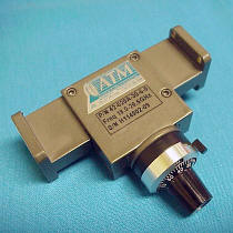
Narda-MITEQ offers continuously variable attenuators covering the waveguide sizes WR28 through WR284 with variable attenuation from 0-30 dB.
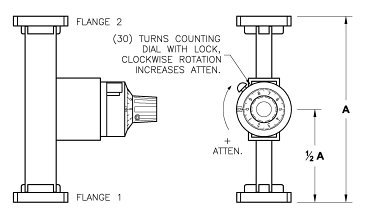
Construction includes a multi-turn dial useful for adjusting attenuation, and can be calibrated at a spot frequency upon request. All models have a maximum VSWR of 1.15 and maximum insertion loss of 0.5dB.
For more information feel free to call us and discuss your needs with one of our design engineers.
Waveguide Attenuators:
Low Power Fixed Attenuators
Low Power Fixed Precision
High Power Fixed Precision
Coaxial:
Coaxial Attenuators
Ka-Band:
Ka-Band Coaxial Attenuators
Ka-Band Waveguide Attenuators
| Level Adjust Standard Models Waveguide Continuously Variable Attenuators (CVA) |
||||||
|---|---|---|---|---|---|---|
 |
 |
|||||
| WG Size | Freq (GHz) | Power (Watts) |
Standard Model No.* |
Length (L) Inches |
Flatness +/- dB |
Outline Drawing |
| WR284 | 2.60 - 3.95 | 11 | 284-620A-30-6-6 | 10.0 | N/A | Dwg |
| WR229 | 3.30 - 4.90 | 9 | 229-620B-30-2-2 | 9.0 | N/A | Dwg |
| WR187 | 3.95 - 5.85 | 7 | 187-620A-30-6-6 | 8.5 | N/A | Dwg |
| WR159 | 4.9 - 7.05 | 5 | 159-620B-30-2-2 | 8.0 | N/A | Dwg |
| WR137 | 5.95 - 8.20 | 4 | 137-620B-30-2-2 | 6.0 | N/A | Dwg |
| WR112 | 7.05 - 10.0 | 3 | 112-620B-30-6-6 | 5.0 | N/A | Dwg |
| WR90 | 8.20 - 12.4 | 2 | 90-620A-30-6-6 | 4.0 | N/A | Dwg |
| WR75 | 10.0 - 15.0 | 1 | 75-620B-30-6-6 | 3.0 | N/A | Dwg |
| WR62 | 12.4 - 18.0 | 1 | 62-620B-30-6-6 | 3.0 | N/A | Dwg |
| WR51 | 15.0 - 22.0 | 1 | 51-620A-30-6-6 | 3.0 | N/A | |
| WR42 | 18.0 - 26.5 | 1 | 42-620A-30-6-6 | 3.0 | N/A | Dwg |
| WR34 | 22.0 - 33.0 | 1 | 34-620A-30-6-6 | 3.0 | N/A | Dwg |
| WR28 | 26.5 - 40.0 | 1 | 28-620A-30-6-6 | 3.0 | N/A | Dwg |
|
* The Standard Model Numbers above are the most common parts ordered for size, material and flange. However, these models can easily be altered for your needs by using the Model # code system to the left. |
||||||||||||||||||||||||||||||||||||||||||||||||||||||||
| Frequency Flat Models Waveguide Continuously Variable Attenuators (CVA) |
||||||
|---|---|---|---|---|---|---|
 |
 |
|||||
| WG Size | Freq (GHz) | Power (Watts) |
Standard Model No.* |
Length (L) Inches |
Flatness +/- dB |
Outline Drawing |
| WR284 | 2.60 - 3.95 | 11 | 284-AF620A-10-6-6 | 10.0 | Dwg | |
| WR229 | 3.30 - 4.90 | 9 | 229-AF620B-10-2-2 | 9.0 | Dwg | |
| WR187 | 3.95 - 5.85 | 7 | 187-AF620A-10-6-6 | 8.5 | Dwg | |
| WR159 | 4.9 - 7.05 | 5 | 159-AF620B-10-2-2 | 8.0 | Dwg | |
| WR137 | 5.95 - 8.20 | 4 | 137-AF620B-10-2-2 | 6.0 | +/- 1.0dB | Dwg |
| WR112 | 7.05 - 10.0 | 3 | 112-AF620B-10-6-6 | 5.0 | +/- 1.0dB | Dwg |
| WR90 | 8.20 - 12.4 | 2 | 90-AF620A-10-6-6 | 4.0 | +/- 1.0dB | Dwg |
| WR75 | 10.0 - 15.0 | 1 | 75-AF620B-10-6-6 | 3.0 | +/- 1.0dB | Dwg |
| WR75 | 10.0 - 15.0 | 1 | 75-AF620B-20-6-6 | 3.0 | +/- 1.0dB | Dwg |
| WR62 | 12.4 - 18.0 | 1 | 62-AF620B-10-6-6 | 3.0 | +/- 1.5dB | Dwg |
| WR62 | 12.4 - 18.0 | 1 | 62-AF620B-15-6-6 | 3.0 | +/- 1.5dB | Dwg |
| WR51 | 15.0 - 22.0 | 1 | 51-AF620A-10-6-6 | 3.0 | +/- 2.0dB | |
| WR42 | 18.0 - 26.5 | 1 | 42-AF620A-10-6-6 | 3.0 | +/- 3.0dB | Dwg |
| WR34 | 22.0 - 33.0 | 1 | 34-AF620A-10-6-6 | 3.0 | +/- 3.0dB | Dwg |
| WR28 | 26.5 - 40.0 | 1 | 28-AF620A-10-6-6 | 3.0 | +/- 3.0dB | Dwg |
|
* The Standard Model Numbers above are the most common parts ordered for size, material and flange. However, these models can easily be altered for your needs by using the Model # code system to the left. |
||||||||||||||||||||||||||||||||||||||||||||||||||||||||