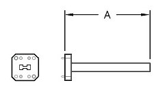
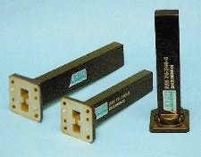
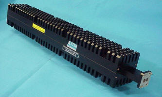
| Double Ridge Waveguide Termination - Low Power and Medium Power - 720/740 Series | ||||||
|---|---|---|---|---|---|---|
|
|
 |
|||||
|
Units are best mounted in the horizontal plane with free air flow. The load temperature will vary depending on power levels and duration. If during use the surface temperature approaches 260°C at the hottest point, (normally where the first fin touches the waveguide body), forced air cooling should be used to prevent damage to the internal load element. Units can survive temperatures as high as 450 °C without damage for a short time. Flange Code: C=Flat, G=Groove, 1=alternate holes, 2=all tapped holes, 3=all thru holes |
||||||
| WG Size | Freq. (GHz) | Standard Model No. |
Avg. Power (Watts) |
Typical VSWR |
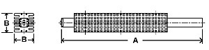
Dim A (Inches) |
Outline Dwg |
| WRD350 | 3.50-8.20 | 350-720-C3 | 1 | 1.05 | 13 | Dwg |
| WRD350 | 3.50-8.20 | 350-740-C3 | 300 | 1.10 | 13 | Dwg |
| WRD475 | 4.75-11.0 | 475-720-C3 | 1 | 1.05 | 8.50 | |
| WRD475 | 4.75-11.0 | 475-740-C3 | 240 | 1.10 | 8.50 | |
| WRD580 | 5.80-16.0 | 580-720-C3 | 1 | 1.05 | 8.50 | |
| WRD580 | 5.80-16.0 | 580-740-C3 | 200 | 1.10 | 8.50 | |
| WRD650 | 6.50-18.0 | 650-720-C3 | 1 | 1.05 | 8.50 | |
| WRD650 | 6.50-18.0 | 650-740-C3 | 200 | 1.10 | 8.50 | |
| WRD750 | 7.50-18.0 | 750-720-C3 | 1 | 1.05 | 8.50 | |
| WRD750 | 7.50-18.0 | 750-740-C3 | 200 | 1.10 | 8.50 | Dwg |
| WRD180 | 18.00-40.0 | 180-720-C3 | 1 | 1.15 | 4.00 | |
| WRD180 | 18.00-40.0 | 180-740-C3 | 30 | 1.15 | 4.00 | |
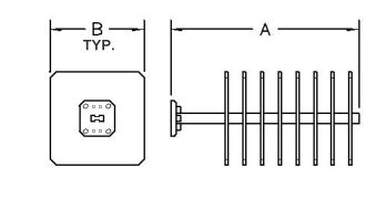
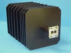
| Double Ridge Waveguide Terminations - High Power - 745 Series | ||||||||
|---|---|---|---|---|---|---|---|---|
|
|
 |
|||||||
|
Units are best mounted in the horizontal plane with free air flow. The load temperature will vary depending on power levels and duration. If during use the surface temperature approaches 260°C at the hottest point, (normally where the first fin touches the waveguide body), forced air cooling should be used to prevent damage to the internal load element. Units can survive temperatures as high as 450 °C without damage for a short time. Flange Code: C=Flat, G=Groove, 1=alternate holes, 2=all tapped holes, 3=all thru holes |
||||||||
| WG Size | Freq. (GHz) | Standard Model No. |
Avg. Power Watts |
VSWR | Dim A (In) |
Dim B | Dim C | Outline Dwg |
| WRD200 | 2.00-4.80 | 200-745-700-C3 | 700 | 1.15 | 18.00 | 6.00 | 5.00 | |
| WRD250 | 2.50-7.50 | 250-745-1000-C3 | 1000 | 1.15 | 11.50 | 4.50 | 4.50 | Dwg |
| WRD250 | 2.50-7.50 | 250-745-1500-C3 | 1500 | 1.15 | 11.50 | 5.00 | 5.00 | |
| WRD475 | 4.75-11.0 | 475-745-C3 | 1000 | 1.10 | 12.00 | 6.00 | 6.00 | |
| WRD580 | 5.80-16.0 | 580-745A-C3 | 1000 | 1.10 | 9.50 | 5.00 | 5.00 | Dwg |
| WRD580 | 5.80-16.0 | 580-745-C3 | 750 | 1.10 | 9.50 | 5.00 | 5.00 | Dwg |
| WRD650 | 6.50-18.0 | 650-745-C3 | 700 | 1.10 | 10.00 | 5.00 | 5.00 | Dwg |
| WRD750 | 7.50-18.0 | 750-745-C3 | 700 | 1.10 | 10.00 | 5.00 | Dwg | |
| Double Ridge Waveguide Terminations - Very High Power - 780 Series | |||||||
|---|---|---|---|---|---|---|---|
 |
 |
||||||
|
Units are best mounted in the horizontal plane with free air flow. The load temperature will vary depending on power levels and duration. If during use the surface temperature approaches 260°C at the hottest point, (normally where the first fin touches the waveguide body), forced air cooling should be used to prevent damage to the internal load element. Units can survive temperatures as high as 450 °C without damage for a short time. Flange Code: C=Flat, G=Groove, 1=alternate holes, 2=all tapped holes, 3=all thru holes |
|||||||
| WG Size | Freq. (GHz) | Standard Model No. |
Avg. Power (CW) |
VSWR | Dim A | Dim B | Outline Dwg |
| WRD250 | 2.5-7.5 | 250-780-2200-C3 | 2200 | 1.15 | 38.50 | 5.25x5.65 | Dwg |
| WRD580 | 5.8-16.0 | 580-780-1500-C3 | 1500 | 1.15 | 22.00 | 3.00 | Dwg |
| WRD650 | 6.5-18.0 | 650-780-1500-C3 | 1500 | 1.15 | 22.00 | 3.00 | Dwg |
| WRD750 | 7.5-18.0 | 750-780-1500-C3 | 1500 | 1.15 | 22.00 | 3.00 | Dwg |
| WRD180 | 18.0-40.0 | 180-780-150-C3 | 150 | 1.15 | 10.0 | 2.50 | Dwg |