• Skip to main content
  • Skip to primary sidebar

Narda-ATM - Microwave RF Components Manufacturer

  • Home
  • Products
    • Coaxial Components
    • Ka-Band Satcom
    • Space Qualified
    • Waveguide Components
  • FAQ
    • Frequently Asked Questions
  • Ordering
    • Catalog
    • Credit Card Order Form
    • Ordering Information
    • Request A Quote
    • Sales Representatives
    • Terms And Conditions
  • Calculators
    • Cable Assy Loss Calculations
    • CF 100 Cable Loss
    • CF 135 Cable Loss
    • CF 160 Cable Loss
    • CF 210 Cable Loss
    • CF 300 Cable Loss
    • CF 500 Cable Loss
    • VSWR Calculator
    • Waveguide Gasket Selection
  • Photos
    • Coaxial Photos
    • Waveguide Photos
    • Flight Waveguide Photos
    • ATM Products In Use
  • Technical
    • Cable Assy Loss Calculation
    • Cable Length Tolerances
    • Mil-Spec References
    • Tech Notes
    • Waveguide Gasket Selection
    • Waveguide Flange Sizes & Types
    • Waveguide Info,Rectangular
    • Waveguide Gasket Info
    • Waveguide Info,Dbl Ridge
    • Waveguide Std. Tolerances
  • About ATM
    • Background
    • Contact ATM
    • News and Videos
    • Privacy Policy
    • Quality Control
    • Satisfaction Survey
You are here: Home / Waveguide Components / Terminations / Dummy Loads

Terminations / Dummy Loads

Waveguide Terminations & Dummy Loads

Low, Medium and High Power Terminations

ATM manufactures a tremendous selection of Short, Low, Medium, and High Power Terminations for Rectangular Waveguides that do not require Forced Air Cooling.  Double Ridge Waveguide Terminations are also available.

We offer a complete line of waveguide terminations in all waveguide sizes and power levels.

Please call us and discuss your needs with one of our design engineers.

Waveguide Terminations:
Double Ridge Waveguide Terminations
Water Cooled Terminations
Sliding Adjustable Terminations

Coaxial:
Coaxial Terminations

Ka-Band:
Ka-Band Coaxial Terminations
Ka-Band Waveguide Terminations


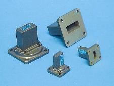
Rectangular Waveguide Termination - Low Power Small Size - 910 Series
Waveguide Terminations - 910 Series
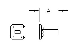
Waveguide Terminations - 910 Series Diagram
  • Full waveguide frequency range.
  • Units pressurized to 15 PSI. Typical - not tested - consult factory for higher pressure requirements and/or if certified data is required.
  • Finish is a unique corrosion-resistant 316 stainless steel epoxy coating.
  • VSWR: 1.2 max., except WR284 - 1.35 max.
  • Series 910 Terminations use Medium Power Elements to achieve low VSWR and stable electrical characteristics.
WG Size Freq. (GHz) Avg. Power
(Watts)
Standard
Model No.*
Dim A.
(Inches)
WR650 1.12-1.70 50 650-910A-2 7.00
WR430 1.70-2.60 40 430-910A-2 7.00
WR340 2.20-3.30 40 340-910A-2 6.00
WR284 2.60-3.95 30 284-910A-6 3.00
WR229 3.30-4.90 25 229-910B-2 3.00
WR187 3.95-5.85 25 187-910A-6 2.50
WR159 4.90-7.05 20 159-910B-2 2.00
WR137 5.85-8.20 15 137-910B-2 1.75
WR112 7.05-10.0 15 112-910B-6 1.50
WR102 7.00-11.0 15 102-910A-6 1.50
WR90 8.20-12.4 15 90-910A-6 1.50
WR75 10.0-15.0 15 75-910B-6 1.25
WR62 12.40-18.0 10 62-910B-6 1.00
WR51 15.0-22.0 10 51-910B-6 1.00
WR42 18.0-26.5 10 42-910B-6 1.00
WR34 22.0-33.0 5 34-910B-6 0.75
WR28 26.5-40.0 5 28-910B-6 0.75
WR22 33.0-50.0 5 22-910B-6 0.75

Ordering Information
Waveguide Terminations
Low Power, Small Size

WR -Mod M -F
Example part number:  42 -910 B -6
Waveguide Size: (WR)
WR22 thru WR650 available
     
Basic Model No.: (-Mod)    
Material (M): A=Aluminum, B=Brass  

Flange (-F): 1=CPRG, 2=CPRF, 6=Cover, 7=Choke*
See ATM Standard Flange page for more info.

* Choke flange will degrade VSWR.


* The Standard Model Numbers above are the most common parts ordered for size, material and flange. However, these models can easily be altered for your needs by using the Model # code system at left.


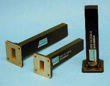
Rectangular Waveguide Termination - Low Power - 920 Series
Low Power Waveguide Terminations - Series 920
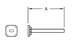
Low Power Waveguide Termination - Series 920 Diagram
  • Full waveguide frequency range.
  • Finish is a unique corrosion-resistant 316 stainless steel epoxy coating.
  • Low outgassing characteristics.
  • VSWR: 1.07 max.
  • ATM Series 920 Terminations use a precision conical element to achieve very low VSWR.
WG Size Freq. (GHz) Avg. Power
(Watts)
Standard
Model No.*
Dim A.
(Inches)
WR650 1.12-1.70 25 650-920A-2 12.50
WR510 1.45-2.20 25 510-920A-2 12.50
WR430 1.70-2.60 15 430-920A-2 11.00
WR340 2.20-3.30 12 340-920A-2 10.75
WR284 2.60-3.95 10 284-920A-6 10.75
WR229 3.30-4.90 10 229-920B-2 7.50
WR187 3.95-5.85 8 187-920A-6 6.25
WR159 4.90-7.05 7 159-920B-2 6.00
WR137 5.85-8.20 6 137-920B-2 5.50
WR112 7.05-10.0 4 112-920B-6 5.00
WR102 7.00-11.0 3 102-920A-6 4.00
WR90 8.2-12.4 4 90-920A-6 4.00
WR75 10.0-15.0 2 75-920B-6 4.00
WR62 12.4-18.0 1.5 62-920B-6 4.00
WR51 15.0-22.0 1.0 51-920B-6 4.00
WR42 18.0-26.5 0.5 42-920B-6 2.50
WR34 22.0-33.0 0.5 34-920B-6 2.50
WR28 26.5-40.0 0.5 28-920B-6 2.00
WR22 33.0-50.0 0.5 22-920B-6 1.75

Ordering Information
Waveguide Terminations
Low Power, 920 Series

WR -Mod M -F
Example part number:  42 -920 B -6
Waveguide Size: (WR)
WR22 thru WR650 available
     
Basic Model No.: (-Mod)    
Material (M): A=Aluminum, B=Brass  

Flange (-F): 1=CPRG, 2=CPRF, 6=Cover, 7=Choke*
See ATM Standard Flange page for more info.

* Choke flange will degrade VSWR.


* The Standard Model Numbers above are the most common parts ordered for size, material and flange. However, these models can easily be altered for your needs by using the Model # code system at left.


Rectangular Waveguide Termination - Medium Power - 940 Series
Medium Power Waveguide Terminations - Series 740
Medium Power Waveguide Terminations - Series 940
Medium Power Waveguide Termination - Series 740 Diagram
Medium Power Waveguide Termination - Series 940 Diagram
  • Full waveguide frequency range.
  • Finish: Hi-Temp black paint. Standard. No paint or TVAC compatible paint available as option - contact factory.
  • Units are best mounted in the horizontal plane with free air flow. The load temperature will vary depending on power levels and duration.
WG Size Freq. (GHz) VSWR
Max.
Avg. Power
(Watts)
Standard
Model No.*
Dim. A
(Inches)
WR650 1.12-1.70 1.15 175 650-940A-2 13.00
WR430 1.70-2.60 1.15 150 430-940A-2 12.00
WR340 2.20-3.30 1.15 150 340-940A-2 12.00
WR284 2.60-3.95 1.10 150 284-940A-6 11.00
WR229 3.30-4.90 1.10 125 229-940B-2 9.75
WR187 3.95-5.85 1.10 100 187-940A-6 8.38
WR159 4.90-7.05 1.10 75 159-940B-2 8.00
WR137 5.85-8.20 1.10 55 137-940B-2 8.00
WR112 7.05-10.0 1.10 40 112-940B-6 7.00
WR102 7.00-11.0 1.10 40 102-940A-6 6.50
WR90 8.2-12.4 1.10 25 90-940A-6 5.50
WR75 10.0-15.0 1.10 25 75-940B-6 4.50
WR62 12.4-18.0 1.10 20 62-940B-6 3.25
WR51 15.0-22.0 1.10 20 51-940A-6 3.25
WR42 18.0-26.5 1.15 15 42-940B-6 3.50
WR34 22.0-33.0 1.15 15 34-940B-6 3.25
WR28 26.5-40.0 1.15 15 28-940B-6 4.00
WR22 33.0-50.0 1.15 15 22-940B-6 2.50

Ordering Information
Waveguide Terminations
Medium Power, Series 940

WR -Mod M -F
Example part number:  51 -940 A -6
Waveguide Size: (WR)
WR22 thru WR650 available
     
Basic Model No.: (-Mod)    
Material (M): A=Aluminum, B=Brass  

Flange (-F): 1=CPRG, 2=CPRF, 6=Cover, 7=Choke*
See ATM Standard Flange page for more info.

* Choke flange will degrade VSWR.


* The Standard Model Numbers above are the most common parts ordered for size, material and flange. However, these models can easily be altered for your needs by using the Model # code system at left.


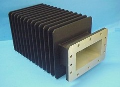
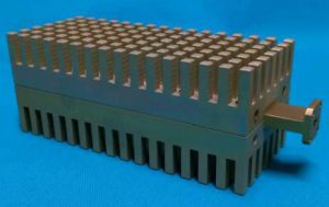
Rectangular Waveguide Termination - High Power - 945 Series
High Power Rectangular Waveguide Termination - Series 945
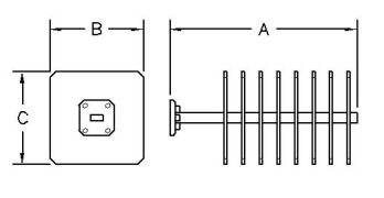
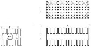
High Power Waveguide Terminations - Series 945 Diagram
  • Full waveguide frequency range.
  • VSWR: See table below.
  • All series 945 Terminations are manufactured from 6061 Aluminum.
  • Finish: Hi-Temp black paint.
  • Units are best mounted in the horizontal plane with free air flow. The load temperature will vary depending on power levels and duration.
WG Size Freq. (GHz) VSWR
Max.
Avg. Power
 (Watts)
Standard
Model No.*
Dim. A
(Inches)
Dim. B
(Inches)
Dim. C
(Inches)
WR650 1.12-1.70 1.2 225 650-945-2 14.00 11.00 9.00
WR430 1.70-2.60 1.2 200 430-945-2 12.00 6.00 6.00
WR340 2.20-3.30 1.2 200 340-945-2 12.00 6.00 6.00
WR284 2.60-3.95 1.10 200 284-945-6 12.00 6.00 5.00
WR229 3.30-4.90 1.10 200 229-945-2 10.63 5.00 5.00
WR187 3.95-5.85 1.10 200 187-945-6 9.00 4.50 4.50
WR159 4.90-7.05 1.10 200 159-945-2 9.00 4.50 4.50
WR137 5.85-8.20 1.10 200 137-945-2 8.50 4.00 4.00
WR137 5.85-8.20 1.10 200 137-945A-2 9.00 4.50 4.50
WR112 7.05-10.0 1.10 175 112-945-6 8.00 4.00 4.00
WR102 7.00-11.0 1.10 175 102-945-6 6.50 3.50 3.50
WR90 8.20-12.4 1.10 150 90-945-6 5.50 3.50 3.50
WR75 10.0-15.0 1.10 150 75-945-6 5.00 3.50 3.50
WR75 10.0-15.0 1.10 150 75-945A-6 5.00 4.50 4.50
WR62 12.4-18.0 1.10 75 62-945-6 4.50 3.00 3.00
WR51 15.0-22.0 1.15 75 51-945-6 4.13 2.25 2.25
 WR51 15.0-22.0 1.15 75 51-945A-6 4.50 3.00 3.00
WR42 18.0-26.5 1.15 50 42-945-6 4.50 2.25 2.25
WR34 22.0-33.0 1.15 50 34-945-6 4.00 2.00 2.00
WR28 26.5-40.0 1.15 40 28-945-6 4.00 2.00 2.00
WR22 33.0-50.0 1.15 30 22-945-6 3.00 1.50 1.50

Ordering Information
Waveguide Terminations
High Power, Series 945

WR -Mod -F
Example part number:  75 -945 -6
Waveguide Size: (WR)
WR22 thru WR650 available
   
Basic Model No.: (-Mod)  

Flange (-F): 1=CPRG, 2=CPRF, 6=Cover, 7=Choke*
See ATM Standard Flange page for more info.

* Choke flange will degrade VSWR.

* The Standard Model Numbers above are the most common parts ordered for size, material and flange. However, these models can easily be altered for your needs by using the Model # code system at left.


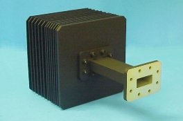
Rectangular Waveguide Termination - Very High Power - 960 Series
Very High Power Waveguide Termination - Series 960
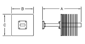
Very High Power Waveguide Termination - Series 960 Diagram
  • Full waveguide frequency.
  • Units may be pressure sealed upon request by adding "/PT" to the model number.
  • Finish: Hi-Temp black paint.
  • VSWR: 1.15 max.
  • Series 960 Terminations are manufactured from 6061 Aluminum.
  • Units are best mounted in the horizontal plane with free air flow. The load temperature will vary depending on power levels and duration.
  • The Avg. Power ratings are worst-case ratings than can be applied continuously. Conditions where Termination is allowed to cool or surface temperature is monitored to not exceed 400 degrees F will increase the Power Rating.
WG Size Freq. (GHz)

Avg.
Power
(Watts)

Standard
Model No.*
Dim. A
(Inches)
Dim. B Dim. C
WR650 1.12-1.70 1600 650-960-2 29.88 16.00 13.25
WR430 1.70-2.60 1500 430-960-2 16.67 9.00 9.00
WR340 2.20-3.30 1400 340-960-2 16.67 9.00 9.00
WR284 2.60-3.95 1400 284-960-6 13.75 6.00 6.00
WR229 3.30-4.90 1200 229-960-2 13.75 6.00 6.00
WR187 3.95-5.85 1000 187-960-6 18.00 6.00 6.00
WR159 4.90-7.05 900 159-960-2 21.50 6.00 6.00
WR137 5.85-8.20 700 137-960-2 18.00 6.00 6.00
WR112 7.05-10.0 600 112-960-6 8.80 5.00 5.00
WR90 8.20-12.4 500 90-960-6 9.81 5.00 5.00
WR75 10.0-15.0 400 75-960-6 7.75 4.50 4.50
WR62 12.4-18.0 350 62-960-6 7.86 4.50 4.50
WR51 15.0-22.0 350 51-960-6 7.75 4.50 4.50
WR42 18.0-26.5 300 42-960-6 5.50 2.25 2.25
WR34 22.0-33.0 300 34-960-6 6.37 2.25 2.25
WR28 26.5-40.0 200 28-960-6 6.56 2.25 2.25

Ordering Information
Waveguide Terminations
Very High Power - 960 Series

WR -Mod -F
Example part number:  75 -960 -6
Waveguide Size: (WR)
WR22 thru WR650 available
   
Basic Model No.: (-Mod)  
Flange (-F): 1=CPRG, 2=CPRF, 6=Cover
See ATM Standard Flange page for more info.

* The Standard Model Numbers above are the most common parts ordered for size, material and flange. However, these models can easily be altered for your needs by using the Model # code system at left.


Rectangular Waveguide Termination - Very High Power - 980 Series
Super High Power Waveguide Termination - 980 Series
Very High Power Waveguide Termination - 980 Series
 
Super High Power Waveguide Termination - 980 Series Diagram
Very High Power Waveguide Termination - 980 Series Diagram
  • Full waveguide frequency.
  • Units may be pressure sealed upon request by adding "/PT" to model number.
  • Finish: Hi-Temp black paint or Chemfilm Conversion Coating only.
  • VSWR: 1.10 typical, 1.15 max.
  • Series 980 Terminations are manufactured from 6061 Aluminum.
  • ATM Series 980 Terminations have specially designed elements that distribute the heat throughout the entire length of the unit to allow for much higher power specifications and uniform heat dissipation.
  • Units are best mounted in the horizontal plane with free air flow. The load temperature will vary depending on power levels and duration.
WG Size Freq. (GHz) Avg. Power
(Watts)
Standard
Model No.*
Dim. A
(Inches)
Dim. B Dim. C
WR112 7.05-10.0 1500 112-980-6 20.00 5.00 5.00
WR90 8.20-12.4 1200 90-980-6      
WR75 10.0-15.0 1000 75-980-6 16.00 3.88 4.48
WR62 12.4-18.0 800 62-980-6      
WR51 15.0-22.0 775 51-980-6 12.00 3.25 3.15
WR42 18.0-26.5 600 42-980-6      
WR34 22.0-33.0 550 34-980-6 6.70 2.50 2.50
WR28 26.5-40.0 500 28-980-6 7.00 2.50 2.50
WR22 33.0-50.0 500 22-980-6 9.00 2.50 2.50

Ordering Information
Waveguide Terminations
Very High Power - 980 Series

WR -Mod -F
Example part number: 28 -980 -6
Waveguide Size: (WR)
WR22 thru WR112 available
   
Basic Model No.: (-Mod)  
Flange (-F): 6=Cover, 8=Cover/Groove
See ATM Standard Flange page for more info.

* The Standard Model Numbers above are the most common parts ordered for size, material and flange. However, these models can easily be altered for your needs by using the Model # code system at left.

For flanges other than shown, please contact the factory.

Note: All 980 series terminations are aluminum construction only.


Primary Sidebar

Search for:

Components Menu

›   Coaxial Components
›   Ka-Band Satcom Components
›   Space Qualified Components
›   Waveguide Components

Latest News and Videos

  • Narda-ATM Re-Certified By NQA for ISO-9001:2015

  • Home
  • Coaxial Components
  • Waveguide Components
  • Ka-Band Components
  • Space Qualified Components

Copyright © 2023 · Narda-ATM