| 06 Series Continuously Variable Attenuators | |||||||
|---|---|---|---|---|---|---|---|
|
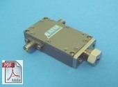
Standard Model |
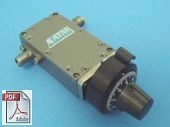
Turns Counting Dial |
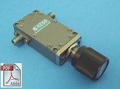
Knob Control Option |
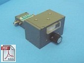
Direct Reading dB Option |
||||
|
|||||||
|
|||||||
| Ka-Band Satcom Level Adjust Models |
|||||
|---|---|---|---|---|---|
| Freq (GHz) | Atten Range dB |
I.L. Max |
VSWR Max |
Flatness +- dB |
Model No. |
| 18.3 - 20.2 | 10 | 0.2 | 1.5 | N/A | AV068Ka-10 |
| 18.3 - 20.2 | 20 | 0.2 | 1.5 | N/A | AV068Ka-20 |
| 18.3 - 20.2 | 30 | 0.2 | 1.5 | N/A | AV068Ka-30 |
| 18.3 - 20.2 | 40 | 0.2 | 1.5 | N/A | AV068Ka-40 |
| 18.3 - 31.0 | 10 | 1.0 | 2.0 | N/A | AV06Ka-10 |
| 18.3 - 31.0 | 20 | 1.0 | 2.0 | N/A | AV06Ka-20 |
| 18.3 - 31.0 | 30 | 1.0 | 2.0 | N/A | AV06Ka-30 |
| 18.3 - 31.0 | 40 | 1.0 | 2.0 | N/A | AV06Ka-40 |
| 27.5 - 31.0 | 10 | 0.7 | 1.5 | N/A | AV069Ka-10 |
| 27.5 - 31.0 | 20 | 0.7 | 1.5 | N/A | AV069Ka-20 |
| 27.5 - 31.0 | 30 | 0.7 | 1.5 | N/A | AV069Ka-30 |
| 27.5 - 31.0 | 40 | 0.7 | 1.5 | N/A | AV069Ka-40 |
| Ka-Band Satcom Frequency Flat Models |
|||||
|---|---|---|---|---|---|
| Freq (GHz) | Atten Range dB |
I.L. Max |
VSWR Max |
Flatness +/- dB |
Model No. |
| 18.3 - 20.2 | 10 | 0.2 | 1.5 | 0.10 | AF068Ka-10 |
| 18.3 - 20.2 | 20 | 0.2 | 1.5 | 0.10 | AF068Ka-20 |
| 18.3 - 20.2 | 30 | 0.2 | 1.5 | 0.15 | AF068Ka-30 |
| 18.3 - 20.2 | 40 | 0.2 | 1.5 | 0.25 | AF068Ka-40 |
| 18.3 - 31.0 | 10 | 1.0 | 2.0 | 1.00 | AF06Ka-10 |
| 18.3 - 31.0 | 20 | 1.0 | 2.0 | 1.25 | AF06Ka-20 |
| 18.3 - 31.0 | 30 | 1.0 | 2.0 | 1.50 | AF06Ka-30 |
| 18.3 - 31.0 | 40 | 1.0 | 2.0 | 2.50 | AF06Ka-40 |
| 27.5 - 31.0 | 10 | 0.7 | 1.5 | 0.25 | AF069Ka-10 |
| 27.5 - 31.0 | 20 | 0.7 | 1.5 | 0.25 | AF069Ka-20 |
| 27.5 - 31.0 | 30 | 0.7 | 1.5 | 0.30 | AF069Ka-30 |
| 27.5 - 31.0 | 40 | 0.7 | 1.5 | 0.60 | AF069Ka-40 |