| Microwave ENR Noise Sources - General Specifications | |
|---|---|
Product Details:
|
Basic Relationships:
• dB ENR = 10 log((T1/T0)-1) • Pn = KTB • T0 = 290K • T is in degrees KELVIN • K = 1.38x10(-23 power) • B is in Hertz • Excess Noise Ratio = ENR |
| 15.5 db ENR Noise Sources - SMA | |||||||||||||||
|---|---|---|---|---|---|---|---|---|---|---|---|---|---|---|---|
 |
|
||||||||||||||
| Freq (GHz) | Noise Output ENR (dB) |
VSWR Max. ON/OFF |
Calibration Frequencies |
Model No. | Package* Code |
||||||||||
| 0.01 - 0.15 | 15.5 +/- 1.0 | 1.20:1 | 10, 70, 140, 150 MHz | NX1501R | R | ||||||||||
| 0.01 - 1.60 | 15.5 +/- 1.0 | 1.20:1 | 10, 70, 140 MHz 0.5, 1.0, 1.6 GHz |
NX1502R | R | ||||||||||
| 1.0 - 2.0 | 15.5 +/- 0.5 | 1.20:1 | 0.5 GHz increments | NX1512X | X | ||||||||||
| 2.0 - 4.0 | 15.5 +/- 0.5 | 1.20:1 | 1.0 GHz increments | NX1524X | X | ||||||||||
| 4.0 - 8.0 | 15.5 +/- 0.5 | 1.20:1 | 1.0 GHz increments | NX1548X | X | ||||||||||
| 8.0 - 12.0 | 15.5 +/- 0.5 | 1.35:1 | 1.0 GHz increments | NX15812X | X | ||||||||||
| 12.0 - 18.0 | 15.5 +/- 0.5 | 1.35:1 | 1.0 GHz increments | NX151218X | X | ||||||||||
| 18.0 - 26.5 | 15.5 +/- 1.0 | 1.60:1 | 1.0 GHz increments | NX151826T | T | ||||||||||
| 2.0 - 26.5 | 15.5 +/- 2.0 | 1.60:1 | 1.0 GHz increments | NX15226T | T | ||||||||||
| 2.0 - 38.0 | 15.5 +/- 2.0 | 1.60:1 | 1.0 GHz increments | NX15238T | T | ||||||||||
| 26.5 - 38.0 | 15.5 +/- 1.0 | 1.60:1 | 1.0 GHz increments | NX152638T | T | ||||||||||
| 26.5 - 40.0 | 15.5 +/- 2.0 | 1.60:1 | 1.0 GHz increments | NX152640T | T | ||||||||||
|
*R or S, X or Y, T or V packages may be interchanged depending on input connector requirements. Model number is modified by changing the suffix letter. |
||||||||||||
| 15.5dB ENR Noise Sources - Type N | |||||||||||||
|---|---|---|---|---|---|---|---|---|---|---|---|---|---|
 |
|
||||||||||||
| Freq (GHz) | Noise Output ENR (dB) |
VSWR max ON/OFF |
Calibration Frequencies |
Model No. | Package Code* |
||||||||
| 1.0 - 4.0 | 15.5+/-0.5 | 1.25:1 | 1.0 GHz increments | NX153EZ | Z | ||||||||
| 2.0 - 8.0 | 15.5+/-0.5 | 1.25:1 | 1.0 GHz increments | NX154FZ | Z | ||||||||
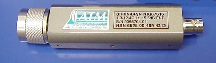
| 1.0 - 12.4 | 15.5+/-0.5 | 1.25:1 | 1.0 GHz increments | NX153GZ | Z | ||||||||
| 4.0 - 12.4 | 15.5+/-0.5 | 1.25:1 | 1.0 GHz increments | NX155GZ | Z | ||||||||
| 1.0 - 18.0 | 15.5+/-1.2 | 1.35:1 | 1.0 GHz increments | NX153HZ | Z | ||||||||
|
*Models offered in package Z are only available in this package, no X or Y substitution can be made. |
|||||||||||||
| High Output ENR / High Freq. Noise Sources | |||||||||||||||
|---|---|---|---|---|---|---|---|---|---|---|---|---|---|---|---|
 |
|
||||||||||||||
| Freq (GHz) | Noise Output ENR (dB) |
Noise Flatness (dB) |
Calibration Frequencies |
Model No. | Package* Code |
||||||||||
| 0.01 - 0.15 | 30 - 36 | +/- 2.0 | 10, 70, 140, 150 MHz | NX3201S | S | ||||||||||
| 0.01 - 1.60 | 30 - 36 | +/- 2.0 | 10, 70, 140 MHz 0.5, 1.0, 1.6 GHz |
NX3202S | S | ||||||||||
| 1.0 - 2.0 | 30 - 35 | +/- 1.0 | 0.5 GHz increments | NX3212Y | Y | ||||||||||
| 2.0 - 4.0 | 30 - 35 | +/- 1.0 | 1.0 GHz increments | NX3224Y | Y | ||||||||||
| 4.0 - 8.0 | 30 - 35 | +/- 1.0 | 1.0 GHz increments | NX3248Y | Y | ||||||||||
| 8.0 - 12.0 | 28 - 33 | +/- 1.0 | 1.0 GHz increments | NX32812Y | Y | ||||||||||
| 12.0 - 18.0 | 26 - 32 | +/- 1.0 | 1.0 GHz increments | NX321218Y | Y | ||||||||||
| 18.0 - 26.5 | 23.0 +/- 1.5 | +/- 1.0 | 1.0 GHz increments | NX321826V | V | ||||||||||
| 2.0 - 26.5 | 23.0 +/- 2.0 | +/- 2.0 | 1.0 GHz increments | NX32226V | V | ||||||||||
| 2.0 - 38.0 | 20.0 +/- 2.0 | +/- 2.0 | 1.0 GHz increments | NX32238V | V | ||||||||||
| 26.5 - 38.0 | 22.0 +/- 1.5 | +/- 1.0 | 1.0 GHz increments | NX322638V | V | ||||||||||
| 26.5 - 40.0 | 22.0 +/- 1.5 | +/- 1.0 | 1.0 GHz increments | NX322640V | V | ||||||||||
|
*R or S, X or Y, T or V packages may be interchanged depending on input connector requirements. Model number is modified by changing the suffix letter. |
||||||||||||