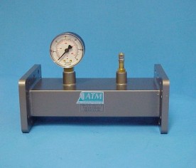
| Waveguide Pressurizing Sections | |||||
|---|---|---|---|---|---|
|
|
 |
||||
| WG Size | Freq. (GHz) | Pressure Section with Gauge |
Pressure Section without Gauge |
||
| Standard Model No.* |
Length (A) (Inches) |
Standard Model No. |
Length (A) (Inches) |
||
| WR650 | 1.12 - 1.70 | 650-210A-2-2 | 6.00 | 650-212A-2-2 | 4.00 |
| WR430 | 1.70 - 2.60 | 430-210A-2-2 | 6.00 | 430-212A-2-2 | 4.00 |
| WR340 | 2.20 - 3.30 | 340-210A-2-2 | 6.00 | 340-212A-2-2 | 4.00 |
| WR284 | 2.60 - 3.95 | 284-210A-6-6 | 6.00 | 284-212A-6-6 | 4.00 |
| WR229 | 3.30 - 4.90 | 229-210B-2-2 | 6.00 | 229-212B-2-2 | 4.00 |
| WR187 | 3.95 - 5.85 | 187-210A-6-6 | 5.00 | 187-212A-6-6 | 3.00 |
| WR159 | 4.9 - 7.05 | 159-210B-2-2 | 5.00 | 159-212B-2-2 | 3.00 |
| WR137 | 5.95 - 8.20 | 137-210B-2-2 | 4.25 | 137-212B-2-2 | 2.25 |
| WR112 | 7.05 - 10.0 | 112-210B-6-6 | 4.25 | 112-212B-6-6 | 2.25 |
| WR90 | 8.20 - 12.4 | 90-210A-6-6 | 4.25 | 90-212A-6-6 | 2.25 |
| WR75 | 10.0 - 15.0 | 75-210B-6-6 | 4.25 | 75-212B-6-6 | 2.25 |
| WR62 | 12.4 - 18.0 | 62-210B-6-6 | 4.25 | 62-212B-6-6 | 2.25 |
| WR51 | 15.0 - 22.0 | 51-210B-6-6 | 4.25 | 51-212B-6-6 | 2.25 |
| WR42 | 18.0 - 26.5 | 42-210B-6-6 | 4.25 | 42-212B-6-6 | 2.25 |
| WR34 | 22.0 - 33.0 | 34-210B-6-6 | 4.25 | 34-212B-6-6 | 2.25 |
| WR28 | 26.5 - 40.0 | 28-210B-6-6 | 4.25 | 28-212B-6-6 | 2.25 |
| WR22 | 33.0 - 50.0 | 22-210B-6-6 | 4.25 | 22-212B-6-6 | 2.25 |
| WR22 | 33.0 - 50.0 | 22-210B-6R-6R | 4.25 | 22-212B-6R-6R | 2.25 |
|
* The Standard Model Numbers above are the most common parts ordered for size, material and flange. However, these models can easily be altered for your needs by using the Model # code system to the left. |
||||||||||||||||||||||||||||||||||||||||||
| Waveguide Flange Spacer Inlets | ||||
|---|---|---|---|---|
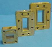 |
GENERAL SPECIFICATIONS
|
|||
| WG Size | Freq. (GHz) | Standard Model No. |
Flange Thickness (Inches) |
Outline Drawings |
| WR650 | 1.12 - 1.70 | 650-211A-2-2 | 0.75 | Dwg |
| WR430 | 1.70 - 2.60 | 430-211A-2-2 | 0.75 | |
| WR340 | 2.20 - 3.30 | 340-211A-2-2 | 0.75 | |
| WR284 | 2.60 - 3.95 | 284-211A-6-6 | 0.75 | |
| WR229 | 3.30 - 4.90 | 229-211B-2-2 | 0.75 | |
| WR187 | 3.95 - 5.85 | 187-211A-6-6 | 0.75 | |
| WR159 | 4.90 - 7.05 | 159-211B-2-2 | 0.75 | |
| WR137 | 5.95 - 8.20 | 137-211B-2-2 | 0.75 | |
| WR112 | 7.05 - 10.0 | 112-211B-6-6 | 0.75 | |
| WR102 | 7.00 - 11.0 | 102-211A-6-6 | 0.75 | |
| WR90 | 8.20 - 12.4 | 90-211A-6-6 | 0.75 | |
| WR75 | 10.0 - 15.0 | 75-211A-6-6 | 0.75 | |
| WR62 | 12.4 - 18.0 | 62-211A-6-6 | 0.75 | |
| WR51 | 15.0 - 22.0 | 51-211A-6-6 | 0.75 | |
| WR42 | 18.0 - 26.5 | 42-211B-6-6 | 0.75 | |
| WR34 | 22.0 - 33.0 | 34-211A-6-6 | 0.75 | |
| WR28 | 26.5 - 40.0 | 28-211A-6-6 | 0.75 | |
|
* The Standard Model Numbers above are the most common parts ordered for size, material and flange. However, these models can easily be altered for your needs by using the Model # code system to the left. |
||||||||||||||||||||||||||||||||||||||||||