• Skip to main content
  • Skip to primary sidebar

Narda-ATM - Microwave RF Components Manufacturer

  • Home
  • Products
    • Coaxial Components
    • Ka-Band Satcom
    • Space Qualified
    • Waveguide Components
  • FAQ
    • Frequently Asked Questions
  • Ordering
    • Catalog
    • Credit Card Order Form
    • Ordering Information
    • Request A Quote
    • Sales Representatives
    • Terms And Conditions
  • Calculators
    • Cable Assy Loss Calculations
    • CF 100 Cable Loss
    • CF 135 Cable Loss
    • CF 160 Cable Loss
    • CF 210 Cable Loss
    • CF 300 Cable Loss
    • CF 500 Cable Loss
    • VSWR Calculator
    • Waveguide Gasket Selection
  • Photos
    • Coaxial Photos
    • Waveguide Photos
    • Flight Waveguide Photos
    • ATM Products In Use
  • Technical
    • Cable Assy Loss Calculation
    • Cable Length Tolerances
    • Mil-Spec References
    • Tech Notes
    • Waveguide Gasket Selection
    • Waveguide Flange Sizes & Types
    • Waveguide Info,Rectangular
    • Waveguide Gasket Info
    • Waveguide Info,Dbl Ridge
    • Waveguide Std. Tolerances
  • About ATM
    • Background
    • Contact ATM
    • News and Videos
    • Privacy Policy
    • Quality Control
    • Satisfaction Survey
You are here: Home / Ka-Band Components / Ka-Band Waveguide / Attenuators / Fixed Attenuators

Fixed Attenuators

Fixed Waveguide Attenuator for Ka-Band

Waveguide Fixed Attenuator For Ka-Band

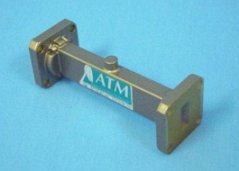
ATM offers a series of fixed rectangular waveguide attenuators covering the Ka-Band at 18.3 - 20.2GHz for the downlink and 27.5 - 31.0GHz for the uplink. Standard waveguide attenuation values are 3dB, 6dB, 10dB, 20dB and 30dB (other attenuation values available, consult factory for details).

Fixed waveguide attenuators are constructed with a precision element for optimum electrical performance, but note that Attenuation vs. Frequency can vary greatly depending on the attenuation at a given frequency. Waveguide Fixed Attenuators with normal and high power units are also available. For more information call us and discuss your needs for waveguide attenuators with one of our design engineers.

Ka-Band Waveguide Attenuators:
Ka-Band WG Fixed Precision
Ka-Band Variable Attenuators
Ka-Band Coaxial Attenuators

Coaxial:
Coaxial Attenuators

Waveguide:
Waveguide Attenuators

Waveguide Fixed Attenuators
Ka-Band, Downlink 18.3 - 20.2GHz, Uplink 27.5 - 31.0GHz
Waveguide Fixed Attenuator
   
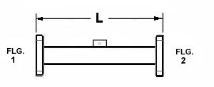
Waveguide Fixed Attenuator - Diagram
 WG Size Freq/ (GHz) WSWR
max
Power
Watt
Calibration
Frequency
Standard
Model No.*
Length (L)
Inches
 WR51 18.3 - 20.2  1.15 1  19.25  51ka-600B-dB-6-6  3.0
 WR42 18.3 - 20.2  1.15 1  19.25  42ka-600B-dB-6-6  3.0
 WR34 27.5 - 31.0  1.20 1  29.25  34ka-600B-dB-6-6  3.0
 WR28 27.5 - 31.0  1.20 1  29.25  28ka-600B-dB-6-6  3.0
Ordering Information
Waveguide Fixed Attenuators for Ka-Band
WR -Mod M -dB -F1 -F2
Example part number:  31ka -600 A -30 -6 -6
Waveguide Size: (WR)
WR28 thru WR51 available
         
Basic Model No.: (-Mod)        
Material (M): A=Aluminum, B=Copper/Brass      
Attenuation (-dB): 3, 6, 10, 20 or 30 std.      
Flange 1 (-F1): 6=Cover, 7=Choke  
Larger Flange (-F2): 1=CPRG, 2=CPRF, 6=Cover, 7=Choke
See ATM Standard Flange page for more info.
 

The Model numbers listed above are the most common model numbers for size, material, flanges, and calibration, however, these models can easily be altered to accommodate customer needs by following the Model # code.

*In addition the customer must choose the attenuation value appropriate for application (3dB, 6dB, 10dB, 20dB, or 30dB) and insert it in the model number where dB is listed.


Primary Sidebar

Search for:

Components Menu

›   Coaxial Components
›   Ka-Band Satcom Components
›   Space Qualified Components
›   Waveguide Components

Latest News and Videos

  • Narda-ATM Re-Certified By NQA for ISO-9001:2015

  • Home
  • Coaxial Components
  • Waveguide Components
  • Ka-Band Components
  • Space Qualified Components

Copyright © 2023 · Narda-ATM