• Skip to main content
  • Skip to primary sidebar

Narda-MITEQ - Microwave RF Components Manufacturer

  • Home
  • About Us
    • Background
    • Contact Narda-MITEQ
    • News and Videos
    • Privacy Policy
    • Quality Control
    • Satisfaction Survey
  • Products
    • Coaxial Components
    • Ka-Band Satcom
    • Space Qualified
    • Waveguide Components
  • FAQ
    • Frequently Asked Questions
  • Ordering
    • Catalog
    • Credit Card Order Form
    • Ordering Information
    • Request A Quote
    • Sales Representatives
    • Terms And Conditions
  • Photos
    • Coaxial Photos
    • Waveguide Photos
    • Flight Waveguide Photos
    • Narda-MITEQ Products In Use
  • Technical
    • Cable Assy Loss Calculation
    • Cable Length Tolerances
    • Mil-Spec References
    • Tech Notes
    • Waveguide Gasket Selection
    • Waveguide Flange Sizes & Types
    • Waveguide Info,Rectangular
    • Waveguide Gasket Info
    • Waveguide Info,Dbl Ridge
    • Waveguide Std. Tolerances
You are here: Home / Calculators / VSWR Calculator

VSWR Calculator

VSWR Calculator

The VSWR Calculator uses the Root-Sum-of-Squares (RSS) Analysis to calculate the most probable VSWR values in a single waveguide assembly with multiple bends, twists, or a chain of Waveguide Assemblies when added together.   To use the calculator, enter the VSWR value for each of the assembly components being added.

Enter VSWR of up to 8 components. If you have less than 8 components, leave the unused inputs as 1.0.

If you need further assistance please scroll down for more detailed instructions for how to use the VSWR Calculator.

divline

How To Use The VSWR Calculator

Example 1

Waveguide Fixed Attenuator Assembly

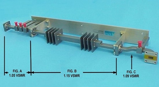
This diagram illustrates how multiple elements contribute to the total VSWR of a typical W/G subassembly.  In the above case, elements of interest such as a triple crossguide coupler at figure A, a fixed attenuator at fig. B, and a crossguide coupler with multiple bends at fig. C are shown with their corresponding contributing VSWR values.  By entering the values given above into the VSWR calculator, we see that the probable assembly-chain VSWR of: 1.05 + 1.15 + 1.09  = 1.19

Example 2

To use the calculator, enter the VSWR value for each of the assembly components being added, as exampled below. 

(3) ea 90°E-Bend - 1.05 VSWR max
(1) ea Flex Assy - 1.12 VSWR max

For this assembly you would enter:
Input VSWR #1 = 1.05
Input VSWR #2 = 1.05
Input VSWR #3 = 1.05
Input VSWR #4 = 1.12
Input VSWR #5 = 1.0
Input VSWR #6 = 1.0
Input VSWR #7 = 1.0
Input VSWR #8 = 1.0

The probable VSWR of the chain is 1.15 max

Example 3

284_flexassy

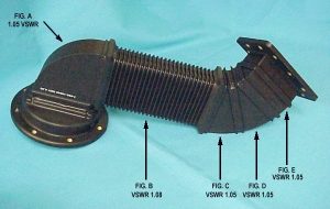
This diagram illustrates how multiple elements contribute to the total VSWR of a typical waveguide subassembly.  In the above case, elements of interest such as: Cast Miters at figures A, C, D, and E, and a Flex WG section at Fig. B, are shown with their corresponding contributing VSWR values.  By entering the values given above into the VSWR calculator, we see that the probable assembly-chain VSWR of: 1.05 + 1.08 + 1.05 + 1.05 + 1.05 = 1.13

Example 4

To use the calculator, enter the VSWR value for each of the assembly components being added, as exampled below. 

(3) ea Miter Bend - 1.03 VSWR max

For this assembly you would enter:
Input VSWR #1 = 1.03
Input VSWR #2 = 1.03
Input VSWR #3 = 1.03
Input VSWR #4 = 1.0
Input VSWR #5 = 1.0
Input VSWR #6 = 1.0
Input VSWR #7 = 1.0
Input VSWR #8 = 1.0

The probable VSWR of the chain is 1.05 max

Primary Sidebar

Search for:
NardaMITEQ.com

Components Menu

›   Coaxial Components
›   Ka-Band Satcom Components
›   Space Qualified Components
›   Waveguide Components

Latest News and Videos

  • Narda-MITEQ Re-Certified By NQA for ISO-9001:2015

  • Home
  • Coaxial Components
  • Waveguide Components
  • Ka-Band Components
  • Space Qualified Components

Copyright © 2025 · Narda-MITEQ