• Skip to main content
  • Skip to primary sidebar

Narda-ATM - Microwave RF Components Manufacturer

  • Home
  • Products
    • Coaxial Components
    • Ka-Band Satcom
    • Space Qualified
    • Waveguide Components
  • FAQ
    • Frequently Asked Questions
  • Ordering
    • Catalog
    • Credit Card Order Form
    • Ordering Information
    • Request A Quote
    • Sales Representatives
    • Terms And Conditions
  • Calculators
    • Cable Assy Loss Calculations
    • CF 100 Cable Loss
    • CF 135 Cable Loss
    • CF 160 Cable Loss
    • CF 210 Cable Loss
    • CF 300 Cable Loss
    • CF 500 Cable Loss
    • VSWR Calculator
    • Waveguide Gasket Selection
  • Photos
    • Coaxial Photos
    • Waveguide Photos
    • Flight Waveguide Photos
    • ATM Products In Use
  • Technical
    • Cable Assy Loss Calculation
    • Cable Length Tolerances
    • Mil-Spec References
    • Tech Notes
    • Waveguide Gasket Selection
    • Waveguide Flange Sizes & Types
    • Waveguide Info,Rectangular
    • Waveguide Gasket Info
    • Waveguide Info,Dbl Ridge
    • Waveguide Std. Tolerances
  • About ATM
    • Background
    • Contact ATM
    • News and Videos
    • Privacy Policy
    • Quality Control
    • Satisfaction Survey
You are here: Home / Ka-Band Components / Ka-Band Coaxial / Hybrid Couplers

Hybrid Couplers

90° 3dB Hybrid Couplers For Ka-Band

90° Hybrid 3dB Directional Couplers

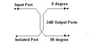
ATM manufactures a variety of 90° Hybrid 3dB directional couplers. Our hybrid directional coupler had two output ports that are 90° out of phase with each other, splitting power equally between it's two output ports.

We offer Ka-Band coax directional hybrid couplers for your next RF project. Models include 20W RF power with 3kW Peak.

For more information feel free to call us and discuss your needs with one of our design engineers.

Ka-Band Couplers:
Ka-Band Coax Directional Couplers
Ka-Band Waveguide Couplers

Coaxial:
Coaxial Couplers
Coaxial 90° Hybrid Couplers

Waveguide:
Waveguide Couplers

Ka-Band Satcom Models - 90° Hybrid 3dB Directional Couplers
  • The Hybrid Directional Coupler splits power equally between its two output ports.
  • Two output ports are 90° out of phase with each other.
  • Construction is stripline in an aluminum housing.
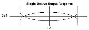
Single Octave Output Response For 3dB Hybrid Couplers
Hybrid Coaxial Couplers - Schematic Diagram
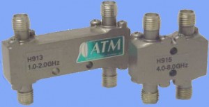
90 degree Hybrid 3dB Directional Coupler for Ka-Band
GENERAL SPECIFICATIONS
RF POWER: 20 watt average
3kw peak
RF CONN: SMA Female or
2.92mm (K-Type) Female- 4 ports


Ka-Band Satcom Models - 90° Hybrid 3dB Directional Couplers
RF Power 20W Avg, 3KW Peak
Freq GHz VSWR
max
Isolation
dB min
Coupling**
Limits dB
Phase
Balance
Model No. Outline
Drawing
18.3 - 20.2 1.60 16 3.2+/-0.55 +/-6.0 H918KaC Fig X
18.3 - 31.0 1.70 14 3.8+/-0.6 +/-9.0 H91Ka Fig X
27.5 - 31.0 1.70 14 3.8+/-0.6 +/-9.0 H919Ka Fig X
** Includes frequency sensitivity. Specifications subject to change without notice.


Primary Sidebar

Search for:

Components Menu

›   Coaxial Components
›   Ka-Band Satcom Components
›   Space Qualified Components
›   Waveguide Components

Latest News and Videos

  • Narda-ATM Re-Certified By NQA for ISO-9001:2015

  • Home
  • Coaxial Components
  • Waveguide Components
  • Ka-Band Components
  • Space Qualified Components

Copyright © 2023 · Narda-ATM